
How to Solve the EMC/EMI on IGBT Inverter Welding Machine
How to solve the EMC/EMI on IGBT inverter welding machine
How to improve the electromagnetic compatibility of inverter welding machines should be a major issue for every welding machine manufacturer.
The electromagnetic compatibility test of welding machines includes two aspects: emission and immunity experiments.
Most of IGBT inverter welding machines use PWM pulse width modulation technology. The current distortion caused by the input rectifier of the welding machine will produce harmonic interference.
Moreover, IGBT will generate a large amount of coupled noise when switching at high speed, which is a source of interference for other electronic and electrical equipment that share the same working environment with the inverter welder. Our practice has proven that it is impossible for an IGBT inverter welding machine without EMC modification measures to pass the emission test. Therefore, what deserves the most attention is how to reduce the electromagnetic emission of the IGBT inverter welding machine to make it comply with the GB15570.10 standard, and then reduce the electromagnetic pollution of the welding machine to the environment.
Main source of interference
Inverter welding machines with metal shells can generally pass the electromagnetic radiation interference test. The two problems of harmonic current emission and power terminal disturbance voltage test exceeding the standard are more prominent.
Low-frequency harmonic disturbance caused by input rectification
When the three-phase 380V power supply enters the welding machine, it must first be rectified by the three-phase rectifier bridge QL1 and filtered by C2. The equivalent capacity of the filter capacitor is generally between 50-1000uf. In a rectifier filter circuit using a large-capacity filter, the rectifier diode conduction time is short, the instantaneous peak value of the filter capacitor charging current is large, and the current waveform is approximately a sharp pulse, which distorts the 50Hz sinusoidal current waveform and generates harmonic currents.
High frequency disturbance caused by inverter
The main circuit of most industrial IGBT inverter welding machines uses a 20kHz full-bridge or half-bridge inverter circuit. When the welding machine's inverter switching device, fast recovery rectifier, and main transformer are running, they will produce electromagnetic interference with high frequency. In addition to the coupling and transmission of high-frequency interference through lines and various channels, the intensity of external radiation in the form of electromagnetic fields is much greater than that of low-frequency harmonic interference.
In the IGBT inverter welding machine, the IGBT works in a high-frequency switching mode at a very high voltage, and the switching voltage and current are close to square waves. The square wave contains rich high-order harmonics, and its spectrum can reach more than 1000 times of the fundamental wave frequency, and its radiation capability is greatly improved.
Suppression of high frequency interference
The power terminal disturbance voltage test frequency band is 150kHz~30MHz. The starting measurement point frequency is much higher than the frequency of the 7th harmonic of the harmonic current. The EMI in the power terminal disturbance voltage test frequency band mainly comes from the inverter. It is enough to suppress the noise in the range of 150kHz~30MHz to a reasonable level.
High-frequency interference mainly occurs in the inverter and output rectifier circuit of the inverter welding machine. This is also the main part where high-frequency interference needs to be suppressed. It can be managed by reducing the interference signals generated by interference sources and preventing the spread of interference signals.
The Application of EMI Filter

It is impossible to completely eliminate the battery harassment generated inside the inverter welding machine. We only need to make the welding machine comply with the requirements of the GB15579.10 standard. The main function of the EMI filter is to prevent attenuation of the power frequency signal with a frequency of 150kHz~30MHz and a frequency of 50Hz, so that the power supply can enter the welding machine smoothly. A reasonable and effective EMI filter should suppress both common-mode and differential-mode interference.
The interference on the power cable has common mode and differential mode current components. Common mode interference is the main control object in IGBT inverter welding machines. The DOREXS DAC4 series is a three-phase EMI filter that takes into account both common mode and differential mode. The figure below is the circuit diagram of the DAC4 series.
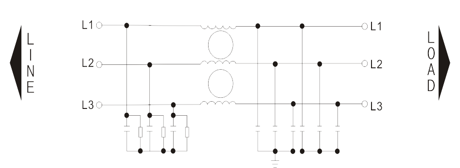
The commonly used magnetic rings to shield interference can only shield some low-frequency interference. High-frequency interference requires EMI filters for shielding. As shown in the figure below, the DOREXS DAC4 series is very suitable for use on the circuit board of an IGBT inverter welding machine to shield high-frequency interference.

After adding the EMI filter, the conduction disturbance in the low-frequency and mid-frequency bands will be significantly reduced, and resonance will appear in the 5-8MHz frequency band. By adjusting circuit parameters, components and installing EMI filters, the power terminal disturbance voltage of the IGBT inverter welding machine can be reduced
DOREXS Manufacturing on EMI Filter
DOREXS has many years of experience in EMI filter manufacturing and is proficient in applying EMI filters to switching power supplies.
Moreover, DOREXS has multiple product certifications, including CE, ISO9001, UL and other certifications, which meet the technical requirements of European and American countries.
About EMI
Introduction to EMC/EMI
Sources of EMC/EMI
Prevention and Mitigation of EMC/EMI
EMC/EMI Protective Materials
Grounding and Layout Optimization
The importance for EMI Filtering in Medical Devices
What is EMI Filter in Power Supply and How Does It Work



