
What Is a Three-Phase EMI Filter? (DOREXS Guide for Industrial and OEM Engineers)
Introduction: What a 3-Phase EMI Filter Does and Why It Matters
A three phase EMI filter is a passive power line filter installed on 3 phase power inputs to suppress conducted electromagnetic interference and keep noise within electromagnetic compatibility limits. It acts as a low-pass filter, allowing standard 50/60 Hz power to pass while blocking high-frequency EMI that would otherwise corrupt nearby electronic equipment or violate regulations.
Three-phase EMI filters suppress noise in high-power applications where single phase power filters cannot handle the current, voltage, or topology demands. Typical installations include industrial machinery, motor drives, frequency converters, large UPS systems, and inverters. The filter sits between the mains supply (L1, L2, L3, protective earth, and sometimes a neutral line) and the load, providing effective noise suppression across a frequency range from 9 kHz or 150 kHz up to 30 MHz, depending on the applicable standard.
This article is written by DOREXS, a manufacturer of EMI filters and EMC solutions, for design engineers and procurement teams who need to understand what a three phase emi filter is before specifying one. DOREXS offers catalog and custom 3 phase EMI filters for delta and wye systems, with current ratings from low tens of amps up to several hundred amps. Three-phase EMI filters are designed to meet IEC and UL safety standards, and they help maintain compliance with federal EMI regulations.
Basics of Three-Phase Power and EMI
Three phase power consists of three sinusoidal voltage waveforms (L1, L2, L3), each offset by 120°, typically at 400 or 480 VAC line to line in industrial grids. A wye system adds a neutral line (4-wire + PE), while delta systems use three wires plus protective earth.
Why industries use three phase power:
-
Higher power density - can distribute power with smaller conductors
-
Smoother torque delivery for motors
-
Better efficiency and lower cabling cost per kW compared to single phase configurations
The main sources of EMI in three phase systems include variable-frequency drives (VFDs), servo drives, SMPS stages, and inverters. High-di/dt switching edges from IGBTs, SiC MOSFETs, and similar devices generate broadband noise that propagates along the phase power line conductors.
Conducted EMI travels via wiring; radiated EMI propagates through space. Three-phase EMI filters are line filters that address the conducted area of the emission spectrum. Common mode noise returns through the earth, while differential mode noise flows between phase conductors. Both modes must be managed to pass EMC tests across the relevant frequency range - typically 150 kHz to 30 MHz for CISPR 11/32, and sometimes starting at 9 kHz for certain industrial standards.
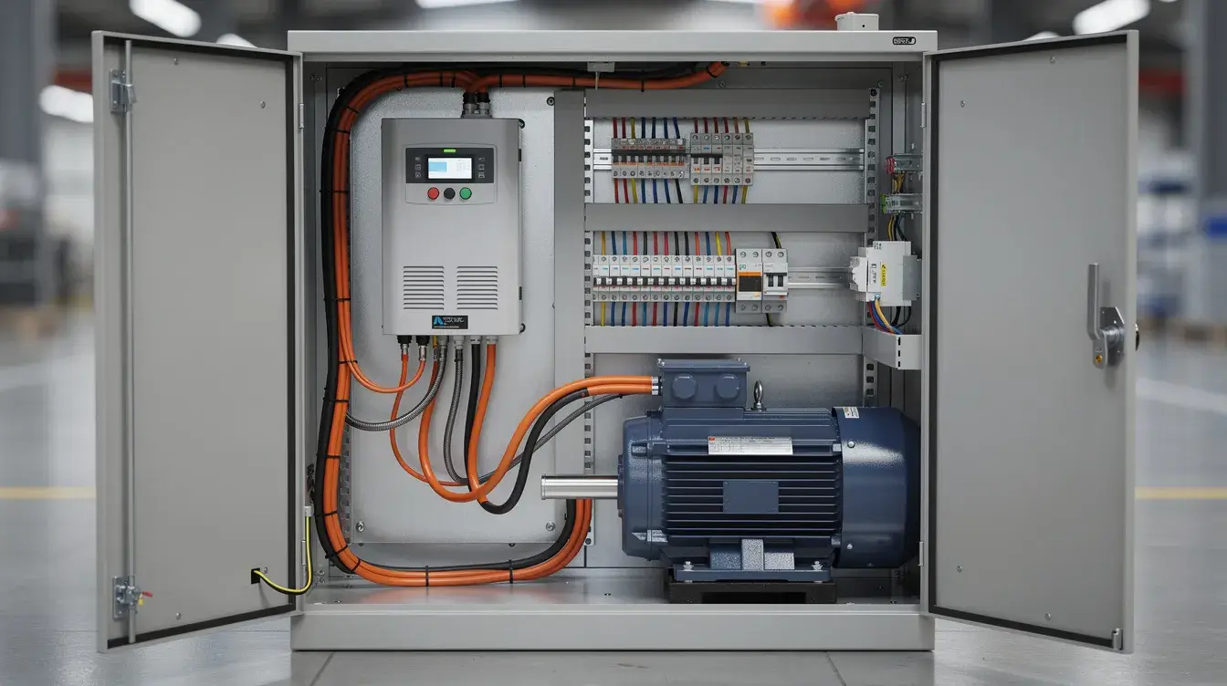
What Is a Three-Phase EMI Filter? Internal Structure and Working Principle
A three phase emi filter is a passive network of inductors, capacitors, and sometimes damping resistors, designed to attenuate high-frequency noise on 3 phase power lines while passing 50/60 Hz with minimal loss. EMI filters protect sensitive equipment from noise on power lines and prevent emissions back to the grid.
The typical internal building blocks of a three-phase EMI filter circuit include:
-
Common mode choke - a three-phase inductor wound so that CM currents see high impedance. Common mode chokes attenuate currents returning through protective earth. Nanocrystalline cores provide wideband performance in common mode chokes, making them a preferred choice in high-performance designs.
-
Differential mode inductors - series inductances that impede DM noise between phases.
-
X capacitors - connected phase-to-phase (or phase-to-neutral in wye systems). X capacitors suppress differential mode noise between phases by providing a low-impedance shunt path at high frequencies.
-
Y capacitors - connected between phase and earth to suppress common mode noise. These safety-rated capacitors divert CM currents to ground before they can affect other devices.
-
Damping resistors / RC networks - prevent LC resonances from creating insertion-loss peaks.
The signal flow is straightforward: [Grid] → [3-phase EMI filter containing CM choke + DM inductors + X & Y caps] → [Motor drive / inverter / industrial controller].
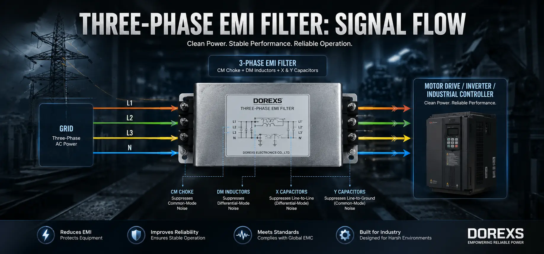
In a "3-wire + PE" (delta) arrangement, X capacitors sit only between phases. In a "4-wire + PE" (wye) configuration, additional phase-to-neutral capacitors and neutral-to-earth Y capacitors are included, changing the overall filter topology. The capacitance value affects leakage current in EMI filters, so the network must be carefully designed for each system type.
Common Mode vs Differential Mode Noise in Three-Phase Systems
Understanding noise modes is the easy way to determine which phase filters and EMC solutions will actually solve your compliance problem.
Differential mode interference refers to noise currents flowing between phase conductors (L1–L2, L2–L3, L1–L3) or between a phase and the neutral line. It typically dominates at lower frequencies around switching frequency harmonics of the motor drive or SMPS.
Common mode interference appears identically on all three lines relative to earth. It tends to dominate the higher MHz range, driven by parasitic capacitances between switching devices, chassis, and ground planes.
Each mode requires different filter elements:
-
CM noise → common mode chokes + Y capacitors
-
DM noise → series inductors + X capacitors
DOREXS three-phase EMI filters are characterized in both modes, with insertion loss curves provided in datasheets so engineers can verify performance against specific EMC test limits at any point in the frequency range.
Delta and Wye Three-Phase EMI Filter Topologies
Selecting the correct line configuration - delta or wye - is critical when specifying a 3 phase emi filter for industrial machinery and motor drives. Filters are available in 3-wire or 4-wire configurations for delta or wye systems in industrial environments.
-
Delta (Δ, 3-wire + PE): Three phase conductors and protective earth, no neutral. Common on compressors, pumps, and many 480 VAC installations. X capacitors connect phase-to-phase only.
-
Wye (Y / star, 4-wire + PE): Three phases, neutral line, and protective earth. Used when both three-phase loads and single-phase auxiliary loads share the same transformer. A wye filter includes additional phase-to-neutral X capacitors and may add a neutral-to-earth Y capacitor.
Special cases like corner-grounded delta or IT networks require custom EMI filter designs with appropriate insulation and Y-capacitor arrangements.
Real-world examples:
-
A 400 VAC wye system feeding a CNC machine with control electronics and computers on single-phase auxiliaries
-
A 480 VAC delta system powering a large VFD-driven pump motor
-
A 380 VAC star network supplying machine tools with integrated servo drives
Key Specifications When Choosing a Three-Phase EMI Filter
This section serves as a practical checklist for design and procurement teams evaluating phase emi filters for a new three phase platform.
Specification |
What to Check |
| Voltage | Match to grid: 380/400/415 VAC or 480/520 VAC, 50/60 Hz. Verify surge/impulse withstand ratings and maximum continuous voltages. |
| Current | Continuous rating from 6 A to 600 A or more in catalog ranges. High-performance filters can handle currents up to 2500 A. Review derating curves for elevated ambient temperatures. |
| Leakage current | Effective EMI filters require balancing capacitance and leakage current. Systems with RCDs/RCCBs or medical device regulations demand low-leakage designs. |
| Attenuation | Required attenuation is 60 dB at 200 kHz per CISPR B standards. Review insertion loss curves in both CM and DM across the full test frequency range. |
| Safety markings | Look for UL, cUL, ENEC, CE. Confirm compliance suitability for EN 61800-3 (motor drives), CISPR 11 (industrial equipment), or IEC 60601 (medical). |
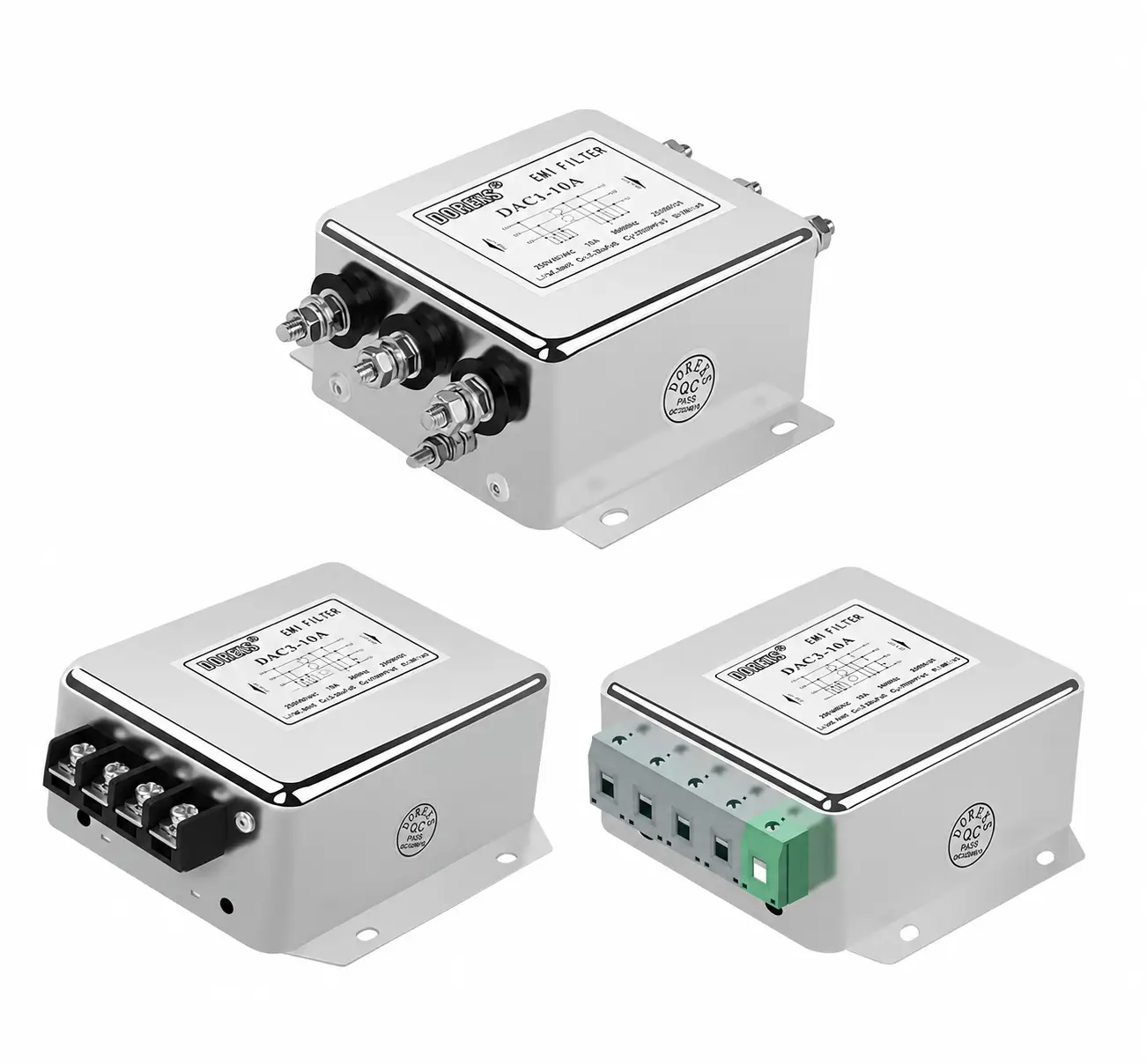
| Mechanical dimension | Book-style, compact low-profile, or chassis mount. Busbar vs terminal-block connections. Ensure the filter fits the cabinet and allows adequate airflow for reducing thermal stress. |
DOREXS supports custom tuning - adjusting component values, adding multi-stage line filters, or optimizing specific frequency bands to pass difficult EMC test points. Explore our C Series (6 A–1000 A) or DAC6 (100 A–200 A) for high-current applications and such applications requiring class-leading performance.
Typical Applications of 3-Phase EMI Filters and How DOREXS Supports Them
Three-phase EMI filters are foundational EMC solutions across high-power industries. EMI filters are utilized in various applications including industrial automation, medical equipment, and renewable energy.
Key applications include:
-
Industrial motor drives, VFD input/output filtering, and inverter EMI suppression
-
CNC machine tools, conveyor systems, compressors, HVAC chillers, and elevators
-
EV fast chargers, solar inverters, and large SMPS or UPS units
-
Medical and laboratory equipment (MRI chillers, centrifuges, imaging systems) where low leakage current and high reliability are critical
-
Robotics cells and devices connected to sensitive PLCs, sensors, and test equipment
They reduce overheating and premature failure of motors and VFDs by suppressing electrical noise. Three-phase EMI filters help equipment meet international EMC regulations like CE and FCC, and even smaller items in mixed-phase installations benefit when paired with matching single-phase EMI filters and transformers from DOREXS.
At DOREXS, the support process starts with analyzing customer schematics and EMI pre-scan data, selecting a suitable catalog filter, then fine-tuning if pre-compliance tests reveal residual peaks. Involve DOREXS early in your design cycle - before manufacturing ramps up - to avoid costly redesigns after failing EMC tests. You can request a consultation at any stage.
Conclusion and How to Work With DOREXS on Three-Phase EMC Solutions
A three phase emi filter is a specialized power line filter for three phase power systems, designed to control common mode and differential mode interference so industrial equipment passes EMC tests and runs reliably. Three-phase EMI filters provide effective noise suppression for high-power applications across all the industries and sectors discussed above.
Key decision points when selecting a filter:
-
System topology - delta and wye, with or without neutral line
-
Voltage, current ratings, and thermal performance features
-
Leakage current limit and RFI compliance for the installed environment
-
Mechanical constraints: cabinet dimension, chassis mounting style
As a dedicated manufacturer of EMI filters and transformers, DOREXS provides engineering support and practical selection help for phase filters used in motor drives, industrial machinery, and medical or test equipment.
Send us your line diagrams, target EMC standards, and preliminary test reports - DOREXS engineers will recommend or design an optimal 3 phase EMI filter solution. From design validation through production ramp-up and after-sales troubleshooting, DOREXS partners with you across the full product life cycle.
How to Choose a Three Phase EMI Filter for Industrial Applications
What Is an EMI Filter? A Practical Guide for Power Electronics and EMC Compliance



