17.5 kW Elevator EMI Remediation Test
Remediation Background
The remediation of the 17.5 kW elevator primarily focuses on filtering the interference noise generated by its frequency conversion system. Three experimental projects were conducted as part of the remediation: radiation testing, conduction testing, and harmonic testing.
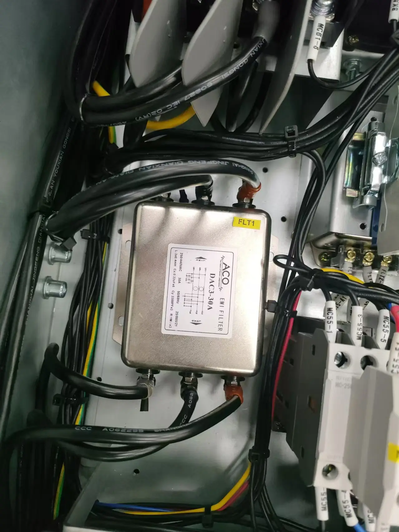
As shown in Figure 1, the previous filter used in the experiment was a 0.4 mH first-stage common-mode filter, but the inductance was too low, which resulted in the failure of the experiment. Our technical team designed a new filter, as shown in Figure 2, with a 6.0 mH filter based on an amorphous magnetic core, in order to achieve the desired experimental results.
 |
 |
| Figure 1 | Figure 2 |
Radiation Testing Remediation
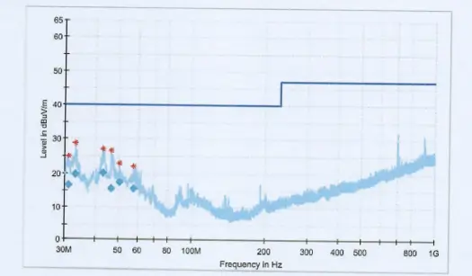
Initially, the internal structure of the enclosure was assembled, and an external motor was connected as a simulated load for testing. The test results, shown in Figure 3, indicated that the radiation levels exceeded the standard between 30 MHz and 43 MHz.
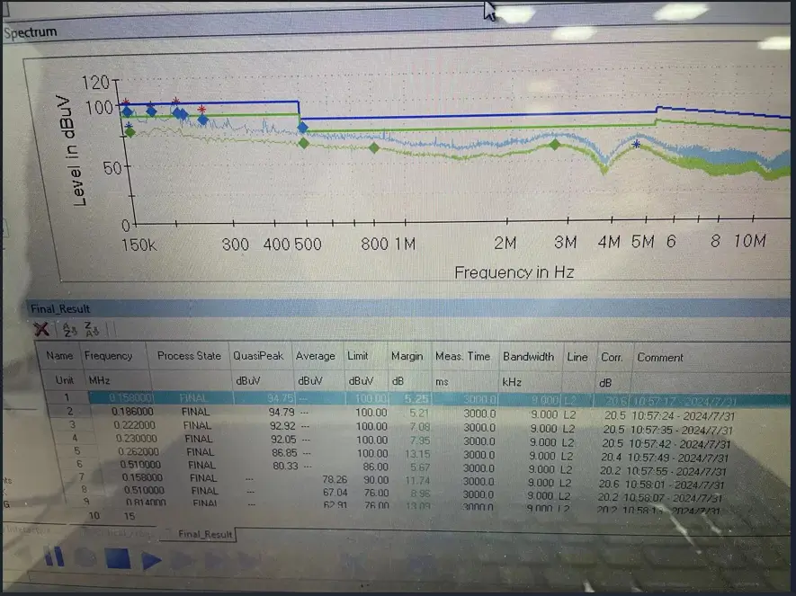 |
| Figure 3 |
Upon observation, it was found that when the signal receiver was positioned directly in front of the simulated load motor, the radiation levels exceeded the standard, with the deviation becoming more pronounced as the power increased. During discussions with the elevator company's engineers, it was revealed that when the enclosure was powered on and the inverter operated normally without the external motor as a load, the radiation test results did not show significant exceedances.
Therefore, it was concluded that, as shown in Figure 4, the exposed motor load, without any shielding measures, acted as a source of radiation interference during the test.
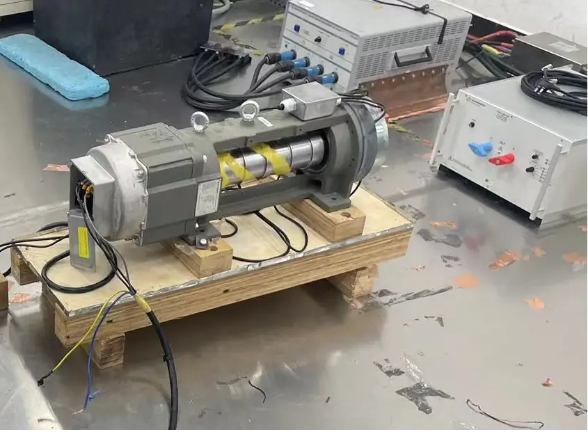 |
| Figure 4 |
Therefore, our technical team added clamp-style ferrite cores to the input and output cables of the enclosure in order to minimize interference from the motor signal during the experiment. Additionally, we discovered that the customer's enclosure was not fully sealed. Due to the presence of an insulating film, the enclosure could not form a completely closed system, leading to uncontrolled radiation signal emission.
After discussing with the testing personnel, our team wrapped the enclosure and cables with copper foil to achieve as close to a fully enclosed state as possible. As shown in Figure 5:
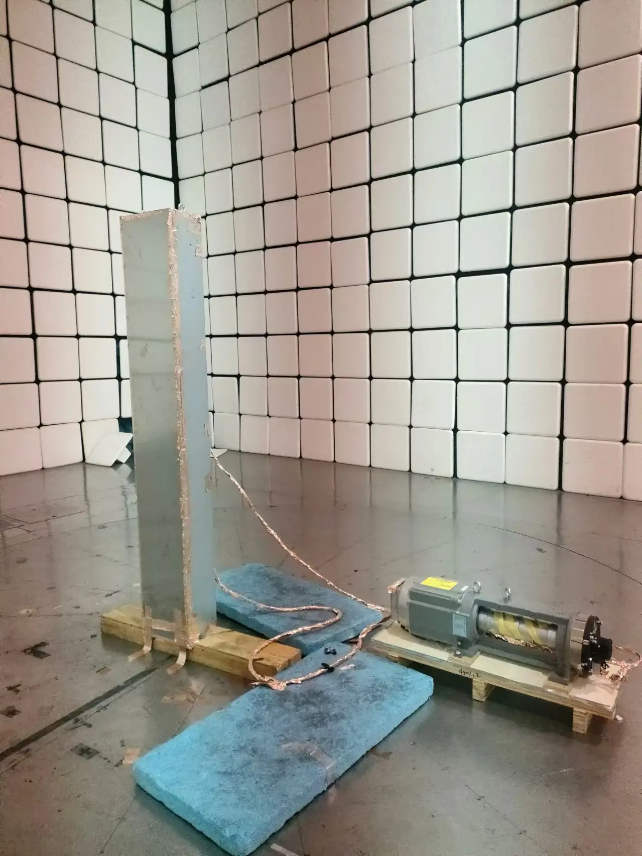 |
| Figure 5 |
 |
| Figure 6 |
Conduction Testing Remediation
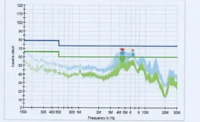
The conduction testing was conducted on the 150 kHz to 30 MHz frequency range for the elevator's enclosure. The original filter used was a three-phase first-stage common-mode 0.4 mH inductor, which did not achieve optimal filtering performance in the lower frequency range.
After analysis by our technical team, it was determined that, based on the inductive reactance formula XL=2πfL, the small inductance failed to provide the required impedance. However, increasing the inductance too much could lead to cross-talk, where differential-mode signals are mistakenly recognized as common-mode signals, significantly affecting the device's immunity to interference.
Considering cost, size, and EMI performance, we replaced the original filter with a three-phase first-stage common-mode 6.0 mH inductor for the remediation. The test results, shown in Figure 7, indicate no exceedances, compliance with the standards, and successful completion of the experiment on the first attempt.
 |
| Figure 7 |
Harmonic Testing Remediation
Harmonic distortion is primarily caused by nonlinear loads in the power grid, and it is commonly mitigated using active filters for harmonic compensation. However, in this remediation project, our technical team determined that the main source of harmonic interference was the frequency conversion system in the elevator's enclosure. As a result, the reactor provided by our company played a role in addressing the harmonic interference.
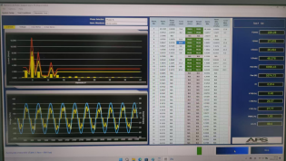
Upon testing, the results, as shown in Figure 8, indicated that only the 5th harmonic exceeded the test standard. After analysis, it was concluded that the reactor's inductance was insufficient. Once the reactor was replaced, the test results, as shown in Figure 9, demonstrated that the system met the required standards and successfully passed the test.
 |
 |
| Figure 8 | Figure 9 |
Summary
2025 DOREXS NEPCON KOREA
DOREXS in Electronica 2024,11.12-11.15
Related Article