EMI Filter Basics: Design, Components, and Applications for Power Supplies and DC-DC Converter
With this foundation, we can now explore the overview of EMI filters and their importance in modern electronic systems.
What Is an EMI Filter?
An EMI filter (Electromagnetic Interference filter) is an electrical device designed to suppress unwanted electromagnetic noise that can disrupt the operation of electronic equipment. Electromagnetic interference (EMI) occurs when unwanted electric currents interrupt the intended currents an electronic device is supposed to receive. EMI can disrupt the operation of any electronic system, including switch mode power supplies and other circuits.
EMI filters are widely used in power supplies, DC-DC converters, industrial equipment, and consumer electronics to ensure that electrical devices meet electromagnetic compatibility (EMC) requirements. EMI filters help limit noise emissions to comply with regulatory standards.
Most electronic products must comply with EMC regulations established by organizations such as the Federal Communications Commission and the International Electrotechnical Commission. Filters ensure compliance with regulatory limits for noise emissions in almost all electronic devices. EMI filters help manufacturers meet these standards by reducing conducted and radiated emissions.

Typical applications include:
-
Medical equipment
-
Industrial automation systems
-
Telecommunications infrastructure
-
Consumer electronics
-
Household appliances
In modern electronic environments, many devices such as smartphones, cell phones, wireless transmitters, and switching power supplies generate electromagnetic noise. Without proper filtering, this noise can interfere with nearby equipment and degrade system performance.
Types of EMI Filters
EMI filters are generally classified into two main categories: passive EMI filters and active EMI filters.
Passive EMI Filters
Passive EMI filters are the most commonly used solution for EMI suppression. They rely on passive electrical components such as inductors and capacitors to block or attenuate high-frequency interference. These filters are typically constructed from discrete components like capacitors and inductors.
Typical passive filter structures include:
-
LC filters
-
Pi (π) filters
-
T filters
-
L filters
These configurations combine inductors and capacitors in different arrangements to achieve the desired attenuation characteristics. Common designs include 'C', 'LC', or 'Pi' networks, which combine capacitors and inductors to maximize noise attenuation. Passive filters work by using reactive components (capacitors and inductors) whose impedance varies with frequency, allowing them to effectively suppress unwanted signals. The performance of passive filters depends on the impedance characteristics of these components across different frequencies.
Engineers often use specific arrangements like Pi filters (C-L-C) or T-filters (L-C-L) depending on the impedance of the source and load when designing EMI filters.
Passive EMI filters are widely used in power supplies, motor drives, and DC-DC converters due to their reliability, simplicity, and cost-effectiveness.
Active EMI Filters
Active EMI filters use active electronic components such as operational amplifiers or control circuits to detect and cancel unwanted noise signals. These filters can provide improved attenuation at lower frequencies compared to passive filters.
However, active EMI filters require an external power source and are generally more complex and expensive to implement.
How EMI Filters Work
Most EMI filters operate as low-pass filters, allowing low-frequency signals such as DC or power-line frequencies to pass while attenuating higher-frequency noise components. EMI filters must operate effectively across a broad frequency range, including higher frequencies generated by modern electronic devices.
The key parameter defining filter behavior is the cutoff frequency, which determines the frequency at which attenuation begins. The cut off frequency is critical in filter design, as it determines the attenuation at a specific frequency and influences the selection of filter components. Filter calculations are often performed at a specific frequency to achieve the desired attenuation and assess filter performance across the intended frequency range.
In practical operation:
-
Capacitors provide a low-impedance path that shunts high-frequency noise to ground. Designers must consider the impedance of capacitors, which varies with frequency, to ensure effective noise suppression.
-
Inductors provide high impedance to high-frequency currents, preventing them from propagating along power or signal lines. The impedance of inductors also changes with frequency and must be considered during design.
Parasitic capacitance, which is unintended capacitance inherent in circuit components and PCB layout, can affect high-frequency performance by causing voltage ripple and high-frequency ringing, especially during switching transitions. The design of EMI filters must account for these parasitic elements, as they can limit high-frequency response, making it necessary to test and validate designs across a range of frequencies.
Together, these components suppress conducted noise and prevent electromagnetic interference from spreading through the system. EMI filters should be designed to provide high impedance over a wide range of frequencies to effectively attenuate unwanted noise.

Effective EMI filtering also depends on:
-
Proper grounding
-
PCB layout optimization
-
Strategic component placement
-
Minimizing parasitic inductance and capacitance
-
Addressing high-frequency noise generated by switching transitions
In many high-performance systems, EMI filters are used together with shielding techniques to address both conducted and radiated noise sources.
Conducted EMI vs Radiated EMI
Electromagnetic interference generally appears in two forms: conducted EMI and radiated EMI.
Conducted EMI
Conducted EMI refers to unwanted electromagnetic noise that travels along electrical conductors such as power cables or signal lines.
This type of interference can propagate through the power distribution network and affect multiple devices connected to the same system.
Engineers typically measure conducted EMI using:
-
Line Impedance Stabilization Networks (LISN)
-
Spectrum analyzers
These tools allow accurate evaluation of noise levels present on power lines.
Radiated EMI
Radiated EMI occurs when electromagnetic noise propagates through space as electromagnetic waves.
This type of interference can affect nearby equipment even without direct electrical connections.
Radiated EMI testing is usually performed inside specialized test environments such as anechoic chambers using antennas and measurement receivers.
Proper EMI filter design can help reduce both conducted and radiated emissions, ensuring that electronic devices comply with international EMC standards.
Key EMI Filter Components
An EMI filter typically includes several key components that work together to suppress noise. Selecting proper components, such as capacitors and inductors, is essential to ensure effective EMI filtering and EMC compliance.
The main parts of an EMI filter are capacitors, inductors, and sometimes resistors. The proper selection of these components—including the right type of capacitors, inductors, and magnetic core materials—is critical for achieving the desired attenuation, impedance matching, and compliance with EMC standards.
Integrating EMI filters early in the design process can help manage unwanted noise more effectively.
Input Capacitors
Input capacitors play a critical role in bypassing high-frequency noise to ground.
Two types of capacitors are commonly used:
X-capacitors
-
Connected between line and neutral
-
Suppress differential-mode noise
Y-capacitors
-
Connected between line and ground
-
Suppress common-mode noise
These capacitors must meet safety standards to ensure reliable operation under high-voltage conditions.
Common Mode Chokes
A common mode choke is designed to suppress common-mode currents by presenting high impedance to currents flowing in the same direction along multiple conductors.
This component is highly effective at reducing noise generated by switching power supplies and other high-frequency circuits.
Differential Mode Inductors
Differential mode inductors are placed in series with the power path to reduce noise voltage between conductors.
They specifically target differential-mode interference while allowing normal power signals to pass.
Input Capacitor Design for DC-DC Converters
In DC-DC converter systems, the design and placement of input capacitors are critical for controlling EMI. EMI filters are often integrated into dc-dc power supplies to mitigate noise and address EMC issues, ensuring compliance with relevant standards and improving overall system performance.
Capacitor Placement
The input capacitor should be located as close as possible to the DC-DC converter input pins. This minimizes parasitic inductance and reduces the loop area of high-frequency switching currents.
Reducing this loop area helps decrease the generation of radiated and conducted noise.
Effect of Capacitor ESR
The equivalent series resistance (ESR) of the input capacitor significantly influences EMI behavior.
-
High ESR can increase voltage ripple
-
Excessive ripple generates additional switching noise
-
Low-ESR capacitors help stabilize converter operation
Selecting capacitors with appropriate ESR characteristics is therefore essential for effective EMI suppression.
Capacitor Sizing
Input capacitors must be sized to balance several factors:
-
Ripple current handling capability
-
Startup inrush current
-
Power supply stability
Oversized capacitors may increase inrush current and stress upstream components, while undersized capacitors may lead to excessive noise.
Common Mode and Differential Mode Currents
Understanding the difference between common mode and differential mode currents is essential for effective EMI filter design. In differential-mode currents, the return path carries equal and opposite RF energy alongside the signal, making it crucial for maintaining circuit balance and minimizing EMI. Effective filtering often depends on proper inductor placement in both the signal and return path. EMI filters use two main approaches—common-mode and differential-mode filtering—to address different types of noise.
Common Mode Currents
Common mode currents flow in the same direction through multiple conductors relative to ground. These currents often originate from switching circuits and parasitic capacitances within the system.
Common mode noise is typically suppressed using:
-
Common mode chokes
-
Y-capacitors
Differential Mode Currents
Differential mode currents flow in opposite directions between two conductors, such as line and neutral.
This type of noise is usually generated by switching regulators and high-speed digital circuits.
Differential noise is typically suppressed using:
-
Series inductors
-
X-capacitors
Selecting the appropriate components for each noise type is essential for achieving optimal EMI filter performance.
Insertion Loss and EMI Filter Performance
Insertion loss measures how effectively an EMI filter attenuates unwanted signals. It is expressed in decibels (dB) and represents the reduction in signal amplitude caused by the filter.
Typical high-performance EMI filters can achieve attenuation levels between 40 dB and 80 dB depending on frequency and topology.
Engineers evaluate filter performance by plotting insertion loss versus frequency, which shows how effectively the filter suppresses noise across the frequency spectrum. Having appropriate test equipment available during testing procedures is essential to accurately verify filter performance and ensure electromagnetic compatibility.
When designing EMI filters, it is important to focus on the frequencies where interference is most problematic and ensure the filter provides sufficient attenuation in that range.
Using simulation software can also help designers determine the best configuration for EMI filters, especially when impedance mismatch is a concern.
EMI Filtering in Power Supplies and DC-DC Converter Systems
EMI filters are widely used in switching power supplies and DC-DC converter systems to prevent switching noise from affecting other circuits. The input supply is a common source of noise, impedance, and voltage fluctuations, so EMI filtering is essential to manage noise originating from the input supply and to ensure stable operation and EMC compliance, and leveraging DOREXS EMI filters can help achieve these performance goals.
Typical integration practices include:
-
Installing the EMI filter at the power entry point
-
Placing surge protection devices upstream of the filter
-
Integrating filter components close to switching stages
To further protect the power supply, an input surge current limiting resistor is included to limit the input surge current when AC voltage is first applied. Metal Oxide Varistors (MOV) are used to absorb voltage transients that may come from the input voltage source. A fuse is placed in series with the input to protect the power source and conductors feeding into the power supply.
EMI filters can assist in meeting immunity and fast transients requirements and radiated emissions as well. Additionally, EMI filters can be used to protect classified data in military/aerospace equipment from failure due to EMI noise.
DC EMI filters are particularly important in high-reliability systems where transient noise, surges, or electromagnetic pulses could damage sensitive electronics.
Designing EMI Input Filters for DC-DC Converters
Designing an effective input filter requires careful consideration of several factors. Identifying the noise source within the device is a critical first step, as it allows engineers to select and optimize EMI filter components and topologies for maximum noise suppression.
EMI filters should be integrated early in the design process to avoid costly rework and to ensure compliance with EMC standards.
Source and Load Impedance
Filter topology should be selected based on the impedance characteristics of the source and load. Improper impedance matching can cause resonance and reduce filter effectiveness.
Simulation and Modeling
Modern filter design often involves simulation tools that incorporate parasitic effects of components such as:
-
Inductor winding capacitance
-
Capacitor ESL
-
PCB trace inductance
Accurate modeling helps predict filter behavior before hardware testing.
Frequency Verification
Engineers should verify insertion loss at the dominant noise frequencies generated by the converter's switching operation.
PCB Layout and Installation Best Practices
The physical implementation of EMI filters has a major impact on performance.
Best practices include:
-
Place filters in close proximity to noise-generating circuits to minimize interference and achieve maximum performance
-
Install filters as close as possible to cable and wire egress (entry or exit) points
-
Avoid crossing input and output traces
-
Minimize loop areas
-
Maintain low-impedance grounding paths
Optimizing the layout on the printed circuit board (PCB) is essential for effective EMI filtering, as PCB design directly impacts noise coupling and filter performance.
For critical applications, the use of a metal shield (metal can shield) can help control crosstalk and radiated noise coupling in EMI filter designs, further reducing radiated EMI coupling.
High Voltage and Safety Considerations
Safety is a critical factor in EMI filter design.
Important design considerations include:
-
Using X-class capacitors for line-to-line connections, and ensuring these capacitors are rated to withstand voltage surges for enhanced safety and reliability
-
Using Y-class capacitors for line-to-ground isolation
-
Limiting leakage current to meet safety regulations
Regulatory standards set limits on input leakage current and influence the selection of safety class capacitors in power supplies. These components must comply with safety standards to ensure reliable operation in high-voltage environments.
Testing and EMC Compliance
Before production, EMI filter performance must be verified through EMC testing. Limiting noise emissions is crucial to comply with EMC regulations such as FCC and European standards, ensuring devices do not disrupt other electronic equipment.
Common measurement methods include:
-
Conducted emissions testing
-
Radiated emissions testing
-
Immunity testing
A Line Impedance Stabilization Network (LISN) is typically used to measure power-line noise during conducted emissions testing.
Spectrum analyzers and current probes help engineers identify noise sources and evaluate filter effectiveness.
EMI filters can also assist in meeting immunity and transient requirements, which is essential for military and aerospace equipment, and project teams can contact DOREXS for EMI filter support when planning qualification and compliance testing.
Selecting EMI Filters for Power Electronics
When selecting EMI filters, engineers must consider several key parameters:
-
Rated current
-
Operating voltage
-
Leakage current limits
-
Required insertion loss
-
Physical size constraints
It is also important to evaluate the effects of transmission lines on EMI propagation, as both differential-mode and common-mode currents can travel along transmission lines and impact radiated emissions. The effectiveness of an EMI filter depends on how well it controls these currents in the context of the system's transmission lines.
In many cases, selecting the optimal filter involves balancing performance, cost, and efficiency.
DOREXS provides high-performance EMI/EMC filters for applications such as power supplies, industrial systems, and communication equipment. Engineering teams can request datasheets, insertion-loss curves, and technical support to ensure the correct filter is selected for their design.
Common EMI Filter Applications
EMI filters are widely used across many industries. They play a crucial role in protecting sensitive devices from EMI noise, which can cause unwanted electrical currents, disrupt device operation, and degrade signal quality, and understanding the principles, functions, and applications of EMI power filters is key to effective design.

Typical applications include:
Medical power supplies
Medical devices require strict EMC compliance to ensure reliable and safe operation.
Industrial automation
Motor drives, PLC systems, and control panels often generate switching noise that must be filtered, making high-efficiency EMI solutions for industrial automation essential in these environments.
Communication equipment
Telecommunications infrastructure relies on EMI filters for data and communication equipment to maintain signal integrity.
Household appliances
Many appliances integrate AC EMI suppression filters at the AC inlet to meet regulatory requirements.
Key applications of EMI filters include filtering high-frequency switching noise in power supplies, ensuring compliance with electromagnetic regulations in appliances and industrial equipment, and protecting sensitive devices in medical equipment from performance degradation, reflecting the broad range of power quality applications for EMI filters.
Troubleshooting EMI Filter Issues
Even properly designed filters can encounter performance issues. Uncontrolled noise in electronic systems can lead to unpredictable behavior and must be addressed promptly.
Common troubleshooting steps include:
-
Measuring noise with a spectrum analyzer
-
Checking insertion loss performance
-
Identifying unexpected resonances
-
Improving grounding paths
In some cases, adding damping networks can reduce ringing and improve filter stability.
Uncontrolled noise can cause system crashes, data corruption, or permanent hardware damage, but EMI filters extend a device's lifespan by protecting sensitive components from electrical stress.
Challenges in EMI Filter Design
Designing EMI filters for modern electronics presents several challenges.
As electronic devices become smaller and faster, switching frequencies increase, generating broader noise spectra. The prevalence of higher frequencies in today's electronic systems, such as switch mode power supplies and other circuits, makes EMI suppression more difficult and requires filters to effectively attenuate noise across a wider frequency range.
Engineers must balance:
-
EMI suppression
-
Power efficiency
-
Cost
-
Physical size constraints
The design of EMI filters must also account for parasitic elements, which can limit the filter's response at higher frequencies and reduce overall effectiveness.
Accurate simulation tools, careful component selection, and EMC testing are essential for overcoming these challenges.
Working With DOREXS for EMI Filter Solutions
Selecting the correct EMI filter can significantly reduce development time and improve system reliability.
DOREXS provides engineering support for:
-
Custom EMI filter design
-
EMC compliance assistance
-
Power supply EMI optimization
-
Industrial and communication system integration
Engineering teams can consult with DOREXS EMI filter experts to identify suitable filter solutions for specific applications.
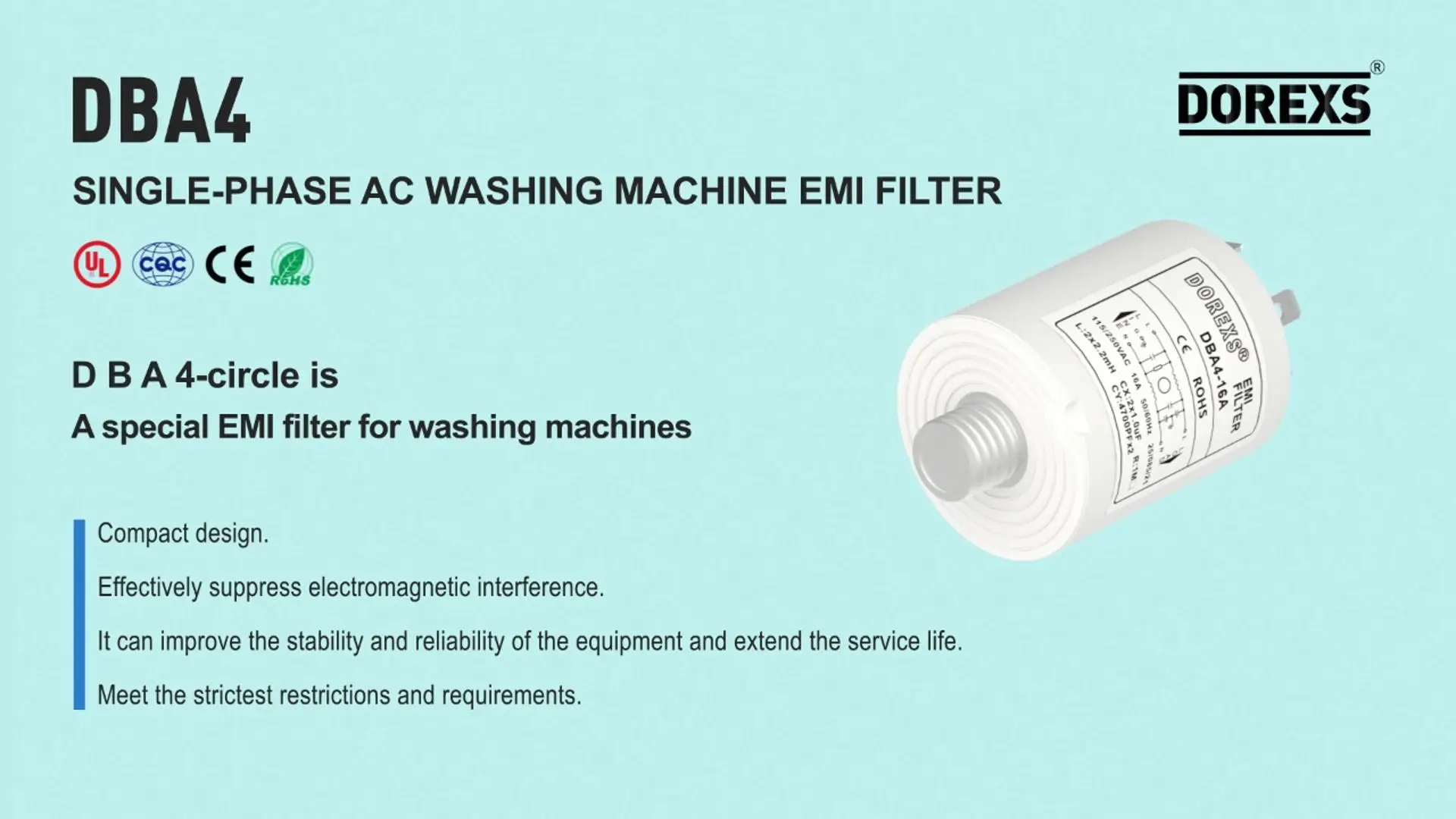
DBA4 Washing Machine EMI Power Filter
Related Article