
EMI Filter Circuit Basics
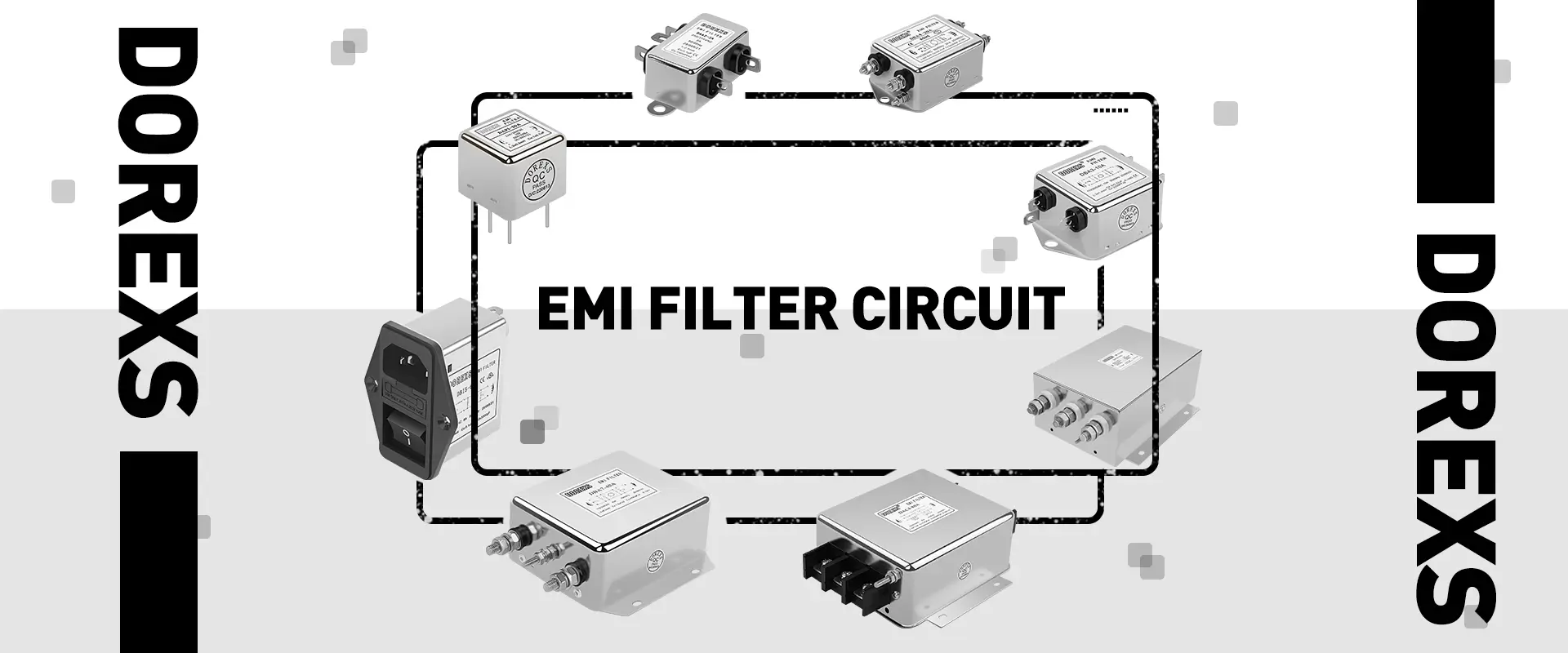
EMI (Electromagnetic Interference) filters are essential components used to suppress or reduce electromagnetic interference in electronic devices. They are widely used in various electronic and electrical equipment to ensure normal operation and electromagnetic compatibility (EMC). Here are some basic concepts about EMI filter circuits.
What is an EMI Filter Circuit?
An EMI filter circuit is a type of circuit designed to suppress or filter electromagnetic interference in electronic devices. It primarily consists of capacitors, inductors, and resistors to filter out high-frequency noise from power lines and signal lines, thus protecting the equipment from electromagnetic interference.
Components of an EMI Filter Circuit
Inductor (L): Includes series inductors and common-mode inductors.
Capacitor (C): Includes parallel capacitors and differential-mode capacitors.
Ferrite Beads: Used to absorb high-frequency noise.
How an EMI Filter Circuit Works
The working principle of an EMI filter circuit is based on the impedance matching characteristics of capacitors, inductors, and ferrite beads. The greater the impedance matching between the input side and output side, or between the power and load sides, the better the attenuation of electromagnetic interference. The filter suppresses interference signals through blocking, absorbing, and reflecting them, ensuring the normal operation of electronic devices.
Designing an EMI Filter Circuit
When designing an EMI filter, it is crucial to consider the input and output characteristics of the circuit as well as the filter's power loss. Analyzing the input and output characteristics involves measuring and calculating voltage, current, and power to ensure the filter performs optimally within its operating range. Power loss refers to the energy loss caused by the filter, which needs to be kept within reasonable limits to avoid adversely affecting the overall circuit performance.
Input and Output Characteristics Analysis
Voltage: Measure and analyze the voltage at the filter's input and output to ensure it can effectively suppress electromagnetic interference without affecting normal signal transmission within its operating voltage range.
Current: Measure the input and output current under different load conditions to ensure the filter operates within its rated current range and avoids overload.
Power: Calculate the input and output power of the filter to ensure it can handle the circuit's power requirements without overheating or damage.
Controlling Power Loss
Power loss is a critical factor in EMI filter design. Excessive power loss can cause the filter to overheat, reducing efficiency and affecting overall circuit performance. Here are some key points for controlling power loss:
Choose appropriate components: Select low-loss inductors and capacitors to minimize energy loss.
Optimize circuit structure: Design a reasonable filter circuit structure to minimize unnecessary losses between components.
Heat dissipation design: For high-power applications, design effective heat dissipation measures, such as adding heat sinks or fans, to prevent the filter from overheating.
Frequency selection: Ensure the filter is designed for the specific interference frequency range relevant to the application to avoid excessive and unnecessary filtering, reducing power loss.
Classification of EMI Filter Circuits
EMI filter circuits can be classified in several ways, as follows:
By Circuit Structure
C-type Filter Circuit: Single capacitor structure, suitable for high impedance sources and high load applications.
LC-type Filter Circuit: Composed of inductor and capacitor elements.
Pi-type Filter Circuit: Consists of two capacitors with an inductor between them.
T-type Filter Circuit: Consists of two inductors with a capacitor between them.
Feed-through Capacitor Filter Circuit: Internal circuits may include C, LC, Pi, T-type filters.
By Filtering Characteristics
Low-pass Filter Circuit: Allows low-frequency signals to pass, blocking high-frequency interference.
High-pass Filter Circuit: Allows high-frequency signals to pass, blocking low-frequency interference.
By Application Type
Signal Line Filter Circuit
Power Line Filter Circuit
By Power Type

DC EMI Filter Circuit
By understanding and selecting the appropriate type and structure of EMI filter circuits, effective filtering solutions can be designed for specific applications, thereby improving the electromagnetic compatibility and overall performance of the equipment.
EMC Filters vs Harmonic Filters: Exploring Their Roles in Electrical Systems
Three Phase EMI Filter Design



