
How to Select a Transformer: A Practical Engineering Guide
Selecting a transformer involves much more than matching an input voltage to an output voltage. The correct transformer must also match the load capacity, phase, frequency, load characteristics, insulation requirements, installation environment, temperature rise, and operating conditions of the equipment.
For industrial equipment manufacturers and electrical engineers, incorrect transformer selection can lead to excessive voltage drop, overheating, nuisance tripping, insufficient starting capacity, poor efficiency, or premature transformer failure.
If you are new to transformer fundamentals, it may help to first understand what a transformer is and how it works.
So, how do you select a transformer correctly?
The basic process is:
Input Voltage → Output Voltage → Phase → Frequency → Load Power → Load Type → Isolation → Environment → Mechanical Requirements → Safety Requirements
This guide explains each factor and shows how to prepare the information required when selecting a standard or custom transformer.
Quick Answer: How Do You Select a Transformer?
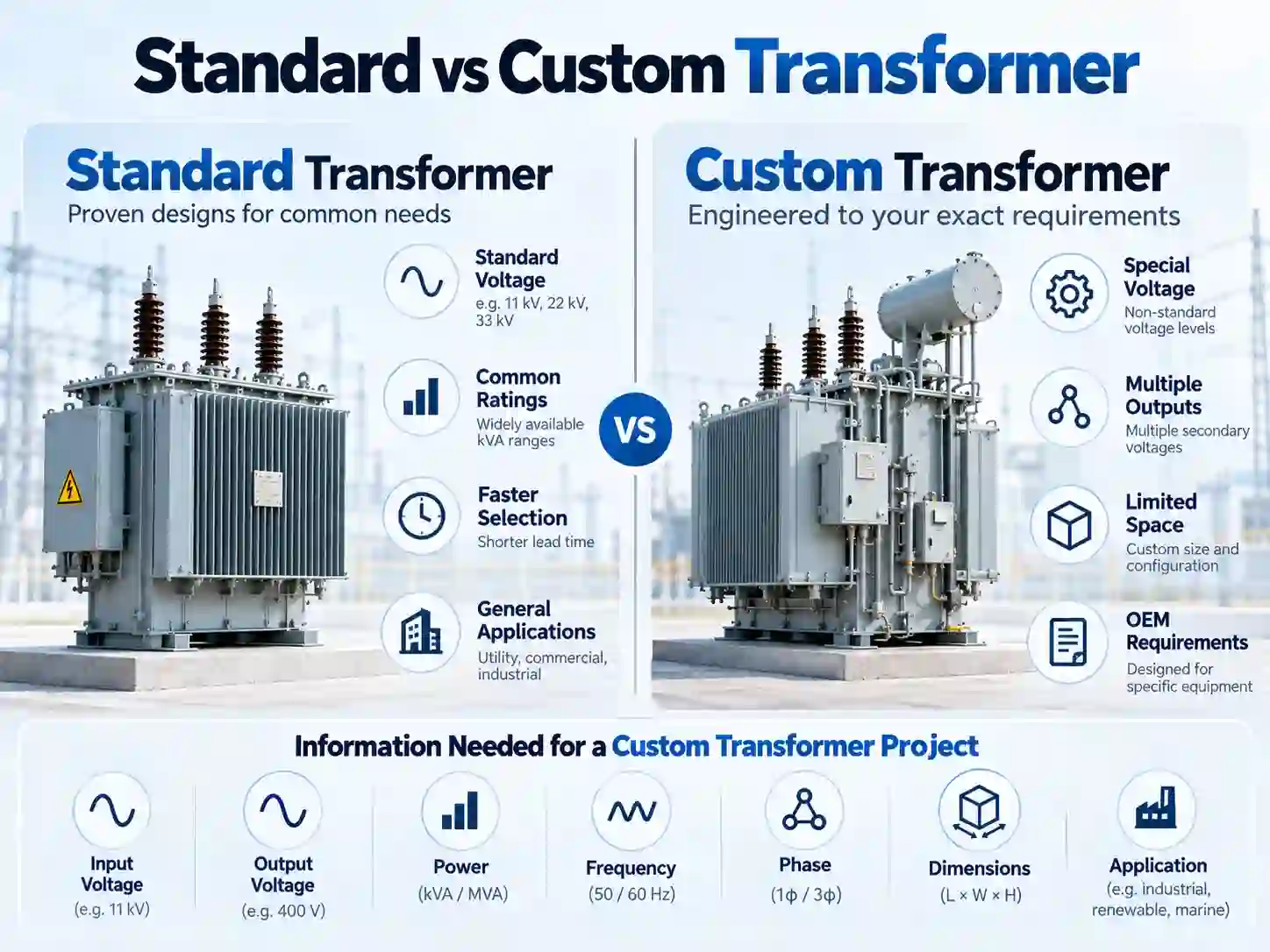
To select a transformer, first determine:
-
Primary input voltage
-
Required secondary output voltage
-
Single-phase or three-phase system
-
Operating frequency
-
Required VA or kVA
-
Load characteristics
-
Electrical isolation requirements
-
Installation environment
-
Mechanical and mounting restrictions
-
Applicable safety and equipment requirements
For a simple resistive or electronic load, voltage and VA/kVA may provide a good starting point.
For motors, contactors, drives, rectifiers, capacitive loads, medical equipment, industrial control systems, or other special applications, additional factors such as inrush current, harmonics, voltage regulation, insulation, temperature rise, and duty cycle must also be evaluated.
DOREXS provides a broad range of power transformers and custom transformer solutions for industrial and OEM equipment.
1. Determine the Primary Input Voltage
The first step in transformer selection is identifying the voltage available from the power source.
This is the primary voltage of the transformer.
Common examples include:
-
110 VAC
-
120 VAC
-
220 VAC
-
230 VAC
-
240 VAC
-
380 VAC
-
400 VAC
-
415 VAC
-
440 VAC
-
480 VAC
However, the nominal voltage alone is not always sufficient.
You should also consider:
-
Normal supply voltage tolerance
-
Minimum and maximum operating voltage
-
Supply frequency
-
Single-phase or three-phase power
-
Expected voltage fluctuations
For OEM equipment sold internationally, multiple input-voltage configurations may also be required.
For example, equipment designed for both European and North American markets may require different transformer primary windings or a transformer with multiple input taps.
2. Determine the Required Secondary Voltage
Next, identify the voltage required by the load.
This becomes the transformer's secondary voltage.
For example:
230 VAC input → 24 VAC output
or:
480 VAC three-phase input → 400 VAC three-phase output
The output voltage should be selected according to the actual operating requirements of the connected equipment rather than simply choosing the closest catalog voltage.
Typical transformer loads include:
-
PLC control circuits
-
Contactors
-
Relays
-
Sensors
-
Industrial controllers
-
Power supplies
-
CNC equipment
-
Communication equipment
-
Medical electronics
-
Motors
-
Heating systems
-
Test equipment
Voltage drop under load should also be considered.
The no-load secondary voltage of a transformer may differ from its voltage at rated load because of winding resistance and internal impedance.
Applications that are sensitive to voltage variation therefore require closer attention to transformer regulation.
For industrial control circuits involving PLCs, relays, contactors and other control devices, a dedicated control transformer may be more suitable than a general-purpose transformer.
3. Select Single-Phase or Three-Phase
The transformer phase configuration should normally match the power system and load architecture.
Single-Phase Transformer
A single-phase transformer is commonly used for:
-
Electronic equipment
-
Control cabinets
-
Small machines
-
Laboratory equipment
-
Communication systems
-
Lighting
-
Medical electronics
-
Residential or light industrial equipment
Single-phase transformers are commonly available in EI-core, toroidal, R-core, isolation, control, and other configurations.
They are particularly useful when equipment is powered from a single-phase AC supply or when individual control circuits require a dedicated voltage conversion stage. For indoor installations, dry type units are often preferred because they avoid oil-related fire concerns.
Three-Phase Transformer
A three-phase transformer is generally more suitable for utility or industrial service where a power transformer typically handles AC power at 400 Hz or less, including:
-
Industrial machinery
-
Manufacturing equipment
-
Motor systems
-
Large control cabinets
-
Power distribution
-
CNC equipment
-
Automation systems
-
Renewable energy equipment
-
High-power industrial loads
When selecting a three-phase transformer, engineers may also need to specify:
-
Primary connection
-
Secondary connection
-
Neutral requirement
-
Winding configuration
-
Phase sequence
-
Vector group, where applicable
For larger power systems, these characteristics can significantly affect system integration.
For applications where natural air cooling, robust construction and industrial power conversion are required, a dry type transformer may be considered, while oil-immersed transformers are often preferred for outdoor, high-power applications.
4. Calculate the Required Transformer VA or kVA
Transformer capacity is normally specified in VA or kVA, rather than watts alone.
Single-Phase Transformer Formula
VA = Voltage × Current
or:
kVA = Voltage × Current / 1000
For example:
A 230 V load drawing 10 A requires:
230 × 10 = 2300 VA
Therefore:
2.3 kVA
The selected transformer must have sufficient capacity for the actual operating load.
Three-Phase Transformer Formula
For a balanced three-phase system:
kVA = √3 × Line Voltage × Line Current / 1000
For example:
400 V × 20 A × 1.732 / 1000
≈ 13.9 kVA
What If the Load Is Given in kW?
If only real power is known:
kVA = kW / Power Factor
For example:
A load requiring 8 kW at a power factor of 0.8 requires approximately:
8 / 0.8 = 10 kVA
However, this is still only the starting point, and accurate load analysis is needed to avoid transformer overload and inefficiency.
The actual transformer rating may need adjustment depending on:
-
Starting current
-
Duty cycle
-
Harmonic content
-
Load diversity
-
Temperature
-
Future expansion
-
Overload requirements
Do not automatically add a large arbitrary safety margin. Transformer capacity should be based on the actual load profile, including peak demand and average loads, as well as actual power demand, load factor, and operating conditions.
5. Consider the Load Type
Two loads with the same rated power can place very different demands on a transformer.
This is one of the most important points when deciding how to select a transformer.
Resistive Loads
Examples include:
-
Heating elements
-
Resistive heaters
These loads are relatively straightforward because starting current is usually not dramatically higher than normal operating current.
Motors
Motors may draw considerably more current during startup than during normal operation.
Transformer selection must therefore consider:
-
Motor starting current
-
Starting method
-
Starting duration
-
Acceptable voltage drop
-
Number of motors starting simultaneously
A transformer selected only according to normal running current may experience excessive voltage sag during motor startup.
In VFD and motor-drive systems, transformer selection should also be considered together with line impedance, harmonic behavior and power-quality requirements. Depending on the system architecture, an electrical reactor may also be used for functions such as current limiting, harmonic mitigation or drive protection.
Contactors, Relays and Solenoids
Industrial control components can have high inrush VA compared with their sealed or holding VA.
For a control transformer, both steady-state VA and simultaneous inrush VA should therefore be evaluated.
DOREXS also offers a dedicated JBK control transformer for industrial control applications.
Rectifier and Capacitive Loads
Rectifiers, switch-mode power supplies and equipment with large DC-link capacitors may draw current in short peaks rather than as a smooth sinusoidal waveform.
This can increase:
-
RMS current
-
Winding heating
-
Harmonic content
-
Voltage distortion
For these applications, simply calculating watts and choosing the nearest transformer size may not be sufficient.
6. Check the Operating Frequency
A transformer must be designed for the intended frequency.
Typical power-frequency transformers operate at:
-
50 Hz
-
60 Hz
-
50/60 Hz
However, transformers are also used at much higher switching frequencies.
Power-Frequency Transformer
Typically used for:
-
Industrial power systems
-
Control power
-
Isolation
-
Voltage conversion
-
Distribution
High-Frequency Transformer
A high-frequency transformer is commonly used in:
-
Switching power supplies
-
Inverters
-
DC-DC converters
-
Charging equipment
-
Power electronics
-
Communication equipment
A transformer designed for 50/60 Hz cannot simply be substituted into a high-frequency switching circuit.
Core material, winding structure, flux density, insulation, losses, leakage inductance and thermal design can all be different.
For power-electronics projects requiring higher power levels or application-specific electrical parameters, DOREXS also provides 1 kW–80 kW high-frequency transformer solutions.
7. Decide Whether Electrical Isolation Is Required
Not all transformers provide the same degree of electrical separation between input and output.
An isolation transformer uses separate primary and secondary windings to provide galvanic isolation.
Isolation transformers may be selected for applications requiring:
-
Electrical separation
-
Equipment protection
-
Improved system safety
-
Grounding configuration control
-
Sensitive electronic equipment
-
Industrial control systems
-
Test equipment
-
Medical or laboratory systems
DOREXS also provides single-phase and three-phase isolation transformers for equipment requiring electrical isolation and voltage conversion.
An autotransformer, by comparison, shares part of the winding between input and output.
Autotransformers can provide advantages in:
-
Size
-
Weight
-
Cost
-
Efficiency
but they do not provide the same galvanic isolation as a transformer with separate windings.
Therefore, before choosing between an autotransformer and an isolation transformer, determine whether electrical isolation is part of the system requirement.
8. Choose the Appropriate Transformer Structure
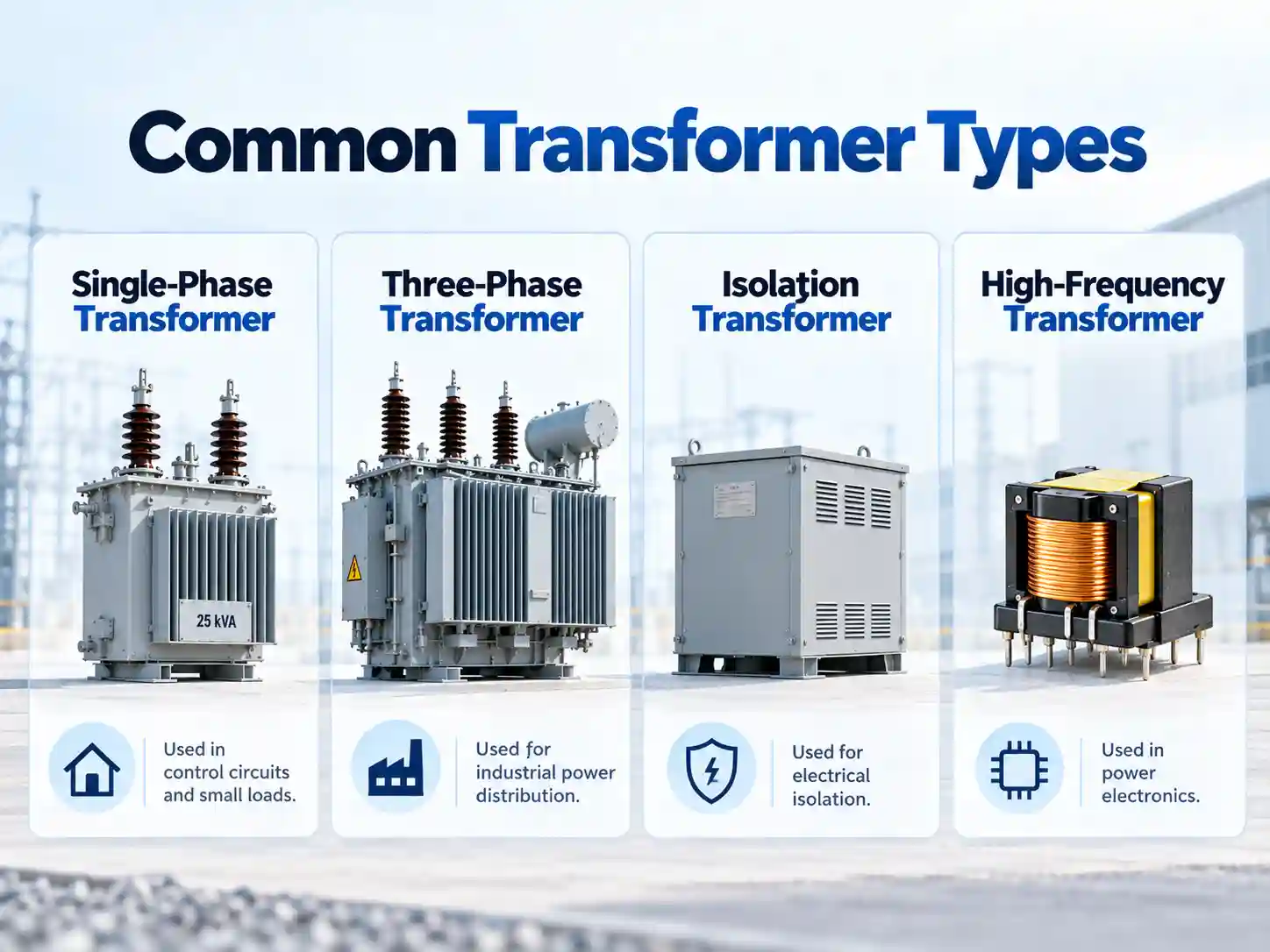
Different transformer constructions suit different equipment designs.
There is no single transformer structure that is best for every application. Transformer construction choices also overlap with the cooling method, commonly including dry-type and liquid-filled designs.
|
Transformer Type |
Typical Advantages |
Common Applications |
|---|---|---|
|
Mature design, flexible, cost-effective |
Industrial control, power supplies, general equipment |
|
|
Compact structure, low stray magnetic field, high efficiency potential |
Medical, audio, instrumentation, power equipment |
|
|
Compact magnetic path, low leakage flux, low-noise potential |
Precision electronics, audio, medical equipment |
|
|
Galvanic separation between circuits |
Industrial, laboratory, medical and sensitive equipment |
|
|
Suitable for three-phase power conversion |
Industrial machinery and power systems |
|
|
Designed for switching frequencies |
SMPS, converters, inverters and power electronics |
|
|
Electrical and mechanical design around specific requirements |
OEM and specialized industrial equipment |
The transformer structure should therefore be selected according to the actual electrical system, space limitations, noise requirements, thermal conditions and cost target.
For example, a toroidal transformer may be attractive where compact size and low stray magnetic field are important, while an EI core transformer may offer greater design flexibility for general industrial and electronic equipment.
An R-core transformer can also be considered for applications requiring compact construction and low magnetic leakage.
9. Evaluate Temperature, Cooling and Installation Environment
Transformer selection should not stop at electrical specifications.
The installation environment can directly influence thermal performance and service life. These environmental factors should also be checked against enclosure or ingress requirements, using NEMA or IP ratings where applicable.
Important factors include:
-
Ambient temperature
-
Ventilation
-
Altitude
-
High humidity
-
Dust
-
Vibration
-
Indoor or outdoor installation
-
Enclosure design
-
Available cooling airflow
-
Mounting orientation
-
Installation space
A transformer installed inside a compact control cabinet may experience much higher surrounding temperatures than the room temperature outside the enclosure, so enclosure layout and ventilation systems matter.
Likewise, high altitude can affect cooling and dielectric performance, and units may need derating above 1000 m because reduced air density impairs cooling. High humidity or moisture can reduce insulation resistance, accelerate aging, and shorten the transformer's lifespan.
When the equipment will operate under unusual environmental conditions, these conditions should be provided to the transformer manufacturer during the design stage.
10. Check Temperature Rise and Insulation Requirements
Transformer losses generate heat.
The thermal design must keep winding and insulation temperatures within acceptable limits under the intended operating conditions.
Important considerations include:
-
Insulation system
-
Winding temperature rise
-
Ambient temperature
-
Ventilation
-
Duty cycle
-
Continuous versus intermittent load
-
Enclosure temperature
A transformer that operates continuously near its thermal limit may have a shorter insulation life than one operating under more moderate conditions. High ambient temperatures can reduce transformer insulation life by roughly 50%, which also works against a long service life.
This is especially important for:
-
Industrial equipment operating 24/7
-
High-density electrical cabinets
-
Medical equipment
-
Renewable-energy systems
-
Power electronics
-
High-temperature environments
11. Consider Efficiency and Transformer Losses
Transformer losses are mainly divided into:
No-Load Losses
These are primarily associated with the magnetic core and exist whenever the transformer is energized.
Load Losses
These increase with load current and include winding resistance losses and other load-dependent effects.
For continuously energized equipment, transformer efficiency can influence:
-
Energy consumption
-
Cabinet temperature
-
Cooling requirements
-
Operating costs
-
Overall equipment efficiency
Simply selecting a much larger transformer does not necessarily improve the system.
A heavily oversized transformer may increase cost, size and no-load losses without providing meaningful operating benefits.
The objective is to select a transformer that matches the expected operating load with appropriate engineering margin.
12. Consider Harmonics and Non-Linear Loads
Modern industrial equipment increasingly contains:
-
Variable frequency drives
-
Servo drives
-
Switching power supplies
-
Rectifiers
-
UPS systems
-
LED drivers
-
Battery chargers
-
Inverters
These are non-linear loads and may generate harmonic currents. In facilities such as data centers, transformers often need to be selected for high harmonic content.
Harmonics can increase transformer heating beyond what would be expected from the fundamental-frequency current alone.
For systems with significant harmonic content, engineers should evaluate:
-
RMS load current
-
Harmonic spectrum
-
Neutral current
-
Transformer heating
-
Derating requirements
-
Winding configuration
-
Application-specific transformer design
The transformer's rated capacity should not be exceeded when harmonic currents are present.
For severe non-linear load conditions, a standard general-purpose transformer should not automatically be assumed to be suitable.
High-frequency conducted noise generated by VFDs, switching power supplies and other power-electronic equipment is also a separate EMC issue. In these applications, an EMI/EMC filter may be required in addition to the transformer.
For switching power supplies in particular, transformer design and EMI filtering for switching power supplies should be evaluated as separate but related parts of the power system.
If harmonic performance must align with regional utility practices, standards such as IEEE C57 are primarily associated with North American grids.
13. Check Mechanical Size and Mounting Requirements
For OEM equipment, mechanical constraints can be just as important as electrical specifications.
Confirm:
-
Maximum width
-
Maximum height
-
Maximum depth
-
Mounting-hole spacing
-
Weight restrictions
-
Terminal location
-
Lead wire length
-
Connector type
-
Installation orientation
-
Required enclosure
This is particularly important for:
-
Control cabinets
-
Medical equipment
-
Laboratory instruments
-
Power supplies
-
Communication equipment
-
Compact industrial machines
When standard transformer dimensions do not fit the equipment, a special application transformer or customized magnetic design may provide a better solution.
14. Consider Applicable Transformer Standards
Transformer requirements vary according to transformer category, voltage, application and target market.
Regulatory compliance is also part of transformer selection, and transformers must comply with IEC 60076 standards where applicable.
Depending on the transformer and end equipment, engineers may need to evaluate requirements related to:
-
Electrical safety
-
Insulation
-
Dielectric strength
-
Temperature rise
-
Creepage and clearance
-
Protective separation
-
Equipment-specific requirements
-
Target-market certification
Different requirements may apply depending on:
-
Transformer type
-
Equipment category
-
Voltage level
-
Installation country
-
End-product certification
-
Medical, railway, industrial or other special application
The applicable standard should therefore be determined at the system level, rather than assuming one standard applies to every transformer. Testing and verification should also be supported by laboratories complying with ISO/IEC 17025.
Transformer Selection Example
Consider an industrial machine requiring a step-down transformer:
-
Input: 400 VAC
-
Three-phase
-
50 Hz
-
Output: 230 VAC
-
Load current: 20 A
-
Continuous industrial operation
A first capacity estimate is:
kVA = 1.732 × 230 × 20 / 1000
≈ 7.97 kVA
An engineer would not immediately purchase an 8 kVA transformer based only on this calculation.
The next questions should include:
-
What type of load is connected?
-
Are motors involved?
-
Is there significant starting current?
-
Are there rectifiers or nonlinear loads?
-
What is the ambient temperature?
-
Will the load expand later?
-
Is isolation required?
-
What voltage regulation is acceptable?
-
Are tap settings or a tap changer needed for input variation?
-
What impedance voltage is required for voltage regulation and short-circuit behavior?
-
What enclosure or installation space is available?
This illustrates why transformer sizing and transformer selection are related but not identical.
The kVA calculation establishes the starting point. The complete application determines the final specification.
For larger industrial three-phase applications, engineers can also compare the required parameters with DOREXS 0.5–100 kVA three-phase dry type transformers.
Common Transformer Selection Mistakes
Selecting Only by kW
Transformers are normally selected according to apparent power in VA or kVA.
Power factor must be considered when converting kW to kVA.
Ignoring Starting Current
Motors, contactors and solenoids may require significantly higher current during startup.
Ignoring Frequency
A transformer must be designed for the intended operating frequency.
Assuming All Step-Down Transformers Provide Isolation
An autotransformer can step voltage down without galvanically isolating the secondary from the primary.
For applications where the primary purpose is voltage conversion, a dedicated 220 V to 110 V step-down transformer may be considered, but isolation requirements should still be confirmed separately.
Oversizing Without Analysis
More capacity is not always better. Excessive oversizing can increase cost, size and no-load losses.
Ignoring Installation Temperature
A transformer mounted inside a poorly ventilated enclosure may operate much hotter than expected.
Ignoring Mechanical Restrictions
A technically suitable transformer is still unusable if it cannot fit into the equipment.
Transformer Selection Checklist
Before requesting a transformer quotation, prepare the following information:
|
Requirement |
Information to Provide |
|---|---|
|
Input Voltage |
Primary voltage and allowable range |
|
Output Voltage |
Required secondary voltage |
|
Phase |
Single-phase / Three-phase |
|
Frequency |
50 Hz / 60 Hz / other |
|
Rated Power |
VA / kVA / kW |
|
Load Current |
Normal and maximum current |
|
Load Type |
Motor / electronics / rectifier / control circuit / other |
|
Isolation |
Required / Not required |
|
Duty |
Continuous / intermittent |
|
Ambient Temperature |
Normal and maximum |
|
Installation |
Indoor / outdoor / cabinet |
|
Size Restrictions |
W × H × D |
|
Mounting |
Chassis / PCB / panel / custom |
|
Connections |
Leads / terminals / connectors |
|
Standards |
Target market or equipment requirement |
|
Quantity |
Prototype and production quantity |
Maintenance planning and vendor technical support should also be considered, since maintenance costs are modest compared with downtime risk. In industrial operations, a transformer failure can cause production losses of about $50,000–100,000 per hour.
Providing this information early can significantly reduce unnecessary design revisions.
Standard or Custom Transformer: Which Should You Choose?
A standard transformer is normally the best choice when:
-
Standard input and output voltages are acceptable
-
Capacity is available in a standard range
-
Mechanical size is not restricted
-
No unusual load conditions exist, and the connected load and installation environment are conventional
A custom or special application transformer becomes useful when the application requires:
-
Special voltage combinations
-
Multiple secondary windings
-
Non-standard VA or kVA
-
Limited installation space
-
Special mounting dimensions
-
Higher isolation requirements
-
Special temperature-rise requirements
-
Unusual operating frequency
-
Special winding configurations
-
OEM-specific connectors or leads
-
Specific fire safety needs that affect the choice between dry-type construction and an oil filled transformer
For OEM equipment, designing the transformer around the electrical and mechanical system can sometimes provide a better solution than designing the equipment around a standard transformer. For liquid filled transformers, natural ester fluids can improve fire safety and are biodegradable compared with mineral oils.
How DOREXS Supports Transformer Selection
DOREXS provides standard and custom transformer solutions for industrial equipment, power electronics, automation systems, communication equipment, medical electronics and other OEM applications.
Available transformer configurations include:
When a standard transformer does not match the equipment, DOREXS can evaluate transformer requirements according to the electrical system, load, installation conditions and mechanical constraints.
For a custom project, the most useful information is:
Input Voltage + Output Voltage + Rated Power + Frequency + Phase + Load Type + Equipment Type + Installation Space + Application Requirements
Providing these parameters allows engineers to determine whether an existing transformer series can be used or whether a custom design is more appropriate.
Frequently Asked Questions
How do I know what size transformer I need?
Calculate the required VA or kVA from the load voltage and current, then evaluate load characteristics such as starting current, harmonics, duty cycle, ambient temperature and future expansion before selecting the final transformer rating.
How do I calculate transformer kVA?
For single-phase systems:
kVA = V × I / 1000
For balanced three-phase systems:
kVA = √3 × V × I / 1000
If load power is given in kW, the power factor must also be considered.
Should I choose a transformer larger than the calculated load?
Some design margin may be appropriate, but the transformer should not be arbitrarily oversized. The correct margin depends on load profile, starting requirements, future expansion, thermal conditions and application requirements.
What is the difference between an isolation transformer and an autotransformer?
An isolation transformer has separate primary and secondary windings and can provide galvanic isolation. An autotransformer shares part of its winding between input and output and therefore does not provide the same electrical isolation.
How do I select a transformer for a motor?
Consider the motor's running current, starting current, starting method, starting duration and allowable voltage drop. In motor applications, also check fault current levels and coordinate protective devices with the transformer and related system components. Selecting a transformer only from motor running power may result in inadequate starting performance.
How do I choose between single-phase and three-phase transformers?
The selection is mainly determined by the available supply and load architecture. Smaller equipment and control circuits commonly use single-phase transformers, while industrial machinery and larger three-phase systems typically use three-phase transformers.
What information is needed for a custom transformer?
At minimum, provide input voltage, output voltage, VA or kVA, frequency, phase, load type, application and installation dimensions.
Special insulation, temperature, wiring, mechanical and certification requirements should also be specified.
For unusual equipment requirements, DOREXS can evaluate a special application transformer according to the actual electrical and mechanical system.
Can a transformer reduce electrical noise?
An isolation transformer can provide galvanic separation and may help with some common-mode coupling or grounding-related problems depending on its design, but a transformer should not automatically be treated as an EMI filter.
Conducted high-frequency interference may require a dedicated EMI/EMC filter, together with appropriate grounding, shielding and cable layout.
Conclusion
Knowing how to select a transformer starts with voltage and power, but reliable transformer selection requires a broader engineering view.
The key factors are:
Primary Voltage + Secondary Voltage + VA/kVA + Phase + Frequency + Load Characteristics + Isolation + Temperature + Installation + Mechanical Requirements
For simple applications, a standard transformer may meet all requirements.
For industrial equipment, medical electronics, power conversion systems, automation equipment and specialized OEM products, load behavior and installation conditions often require additional engineering evaluation.
Choosing the transformer around the actual equipment rather than only a catalog rating helps improve electrical performance, thermal reliability and system integration.
Engineers can explore the complete DOREXS transformer range to compare transformer structures and identify an appropriate starting point for the application.
Need Help Selecting a Transformer?
Not sure which transformer configuration is suitable for your equipment?
Send DOREXS your:
Input Voltage + Output Voltage + Rated Power + Frequency + Phase + Equipment Type + Load Characteristics + Installation Requirements
Our engineering team can evaluate whether a standard transformer or customized transformer configuration is more suitable for your application.
Contact DOREXS for Transformer Selection Support →
Why Do I Need an EMI Filter? A Practical Guide for Equipment Designers



