How Does a Transformer Work? (Engineering Guide by DOREXS)
What Does an Electrical Transformer Do?
Transformers use electromagnetic induction to increase voltage (step up) or decrease voltage (step down) on AC power while keeping power roughly constant. They are stationary devices with no moving parts, and they are crucial in power systems for voltage conversion in generation and distribution.
Every electrical system that moves power from a generator to an end user relies on transformers at multiple points. A generator might produce AC at 20 kV. A power transformer at the plant steps that up to 400 kV for long-distance transmission. At the receiving substation, a step down transformer lowers voltage to 11 kV for distribution, and a final neighborhood unit drops it to 400/230 V for factories and homes. Transformers step up or step down voltage levels at each stage of that chain.

DOREXS designs and manufactures transformers and EMI power filters for industrial automation, medical equipment, and consumer electronics, with a focus on reliability and EMC compliance.
Key benefits of transformers in an electrical system:
-
Efficiency: large power transformers reach 97% to 99.5% efficiency at rated load.
-
High voltage transmission: stepping voltage up reduces current, which cuts I²R losses on transmission lines carrying power over long distances.
-
Safety isolation: transformers electrically isolate circuits for safety and signal integrity by providing galvanic separation between primary and secondary windings.
-
Voltage adaptation: different loads need different voltages; industrial machinery often uses 400 V three phase power, while electronic equipment may need 5 V, 12 V, or 24 V.
Basic Principle: How Do Transformers Work?
Transformers only operate with alternating current (AC) electricity because they rely on a changing magnetic field to transfer energy. Direct current produces a static magnetic field once steady, so it cannot sustain induction in the secondary.
A transformer consists of primary and secondary windings around a magnetic core. These are two coils of wire, electrically insulated from each other, wound on the same core. When alternating current flows through the primary coil, it creates a changing magnetic field in the core. That changing magnetic field induces a voltage in the secondary coil through mutual induction. The two circuits share no conductive connection; energy transfers entirely through magnetic flux.
The voltage ratio depends on the number of turns in the coils. If the primary winding has 100 turns and the secondary winding has 1,000 turns, the output voltage is roughly 10 times the input. Its frequency remains unchanged during the transformation process. For a step down case: 1,000 primary turns and 100 secondary turns yield one-tenth the primary voltage.
Power conservation in an ideal transformer states that input power equals output power. Since electrical power equals voltage times current (P = V × I), when voltage goes up by a factor of 10, electric current drops by a factor of 10. Example: a step-up transformer receives 2 kV at 50 A (100 kW input). The secondary side delivers 20 kV at 5 A (still 100 kW, minus losses).
The Science Behind Transformer Operation
This section gives a slightly deeper physics view for engineers working with transformer specifications and loss calculations. Transformers operate using electromagnetic induction principles first described by Michael Faraday in 1831.
-
Faraday's Law: a changing magnetic flux through a coil induces a voltage proportional to the rate of flux change multiplied by the number of turns. This is the basic function behind every transformer: the faster flux changes, the greater the induced voltage on the secondary side.
-
Ampere's Law: current flows through the primary winding and generates the magnetizing force that drives magnetic flux through the transformer's core. Even at no load, a small magnetizing current (a few percent of rated current) flows to maintain the core's magnetic field.
-
Ohm's Law and load behavior: when a load connects to the secondary, current changes in the secondary cause a reflected current in the primary in inverse proportion to the turns ratio. This is why stepping voltage up on transmission lines reduces current in the conductors.
-
Conservation of energy: input electrical power equals output power plus losses. The main loss categories are copper losses (I²R heating in wire), core losses (hysteresis and eddy currents in the iron core), stray losses from leakage flux, and dielectric losses in insulation materials.
At full load, copper losses dominate. At light load, core losses dominate because they remain nearly constant whenever the transformer is energized. Designers balance these two loss types to hit peak efficiency at the expected operating point.
Main Components of an Electrical Transformer
Modern power transformers share the same main components whether installed in a grid substation or inside a medical device.

-
Magnetic core: laminated grain-oriented silicon steel for 50/60 Hz applications, with lamination thickness around 0.35 mm. For high-frequency or compact units, ferrite or iron powder cores are used. Common core shapes include EI (stacked E and I sheets), UI, and toroidal (ring-shaped, lower leakage inductance). The core carries magnetic flux between the primary and secondary windings.
-
Primary and secondary windings: typically copper conductors with enamel insulation, layered to control voltage gradients. Turn count defines the voltage ratio; wire gauge defines current capacity. Some designs use aluminum where weight or cost trade-offs justify it.
-
Auxiliary features: tap changers adjust voltage ratio to compensate for input variation. Bushings provide insulated conductor passage through the housing. Temperature sensors and thermal protection devices guard against overheating. Electrostatic shields between windings reduce capacitive coupling and EMI.
-
Insulation and dielectric distances: high voltage units use mineral oil, synthetic ester, or epoxy resin. Creepage and clearance distances follow IEC/EN standards. Medical devices often require reinforced insulation with 5 kV DC withstand tests and microamp-level leakage current limits per IEC 60601.
These are the essential components and core components that every engineer should evaluate when specifying a transformer for a given application.
Step-Up vs Step-Down Transformers
Both step up and step down types exist in the same power grid because electrical energy must be converted at each stage between generation and consumption. Transformers allow safe voltage levels for homes and businesses by adjusting voltage at every point in the chain.
Step up transformers:
-
Step-up transformers increase voltage for long-distance transmission. A generator producing 15 to 25 kV feeds a step-up unit that raises voltage to 220 to 500 kV. The higher voltage means lower current for the same power, which reduces losses on transmission conductors.
-
If the primary has 100 turns and the secondary has 2,000 turns, the output voltage is 20 times the input. Current drops by the same factor.
Step down transformers:
-
Step-down transformers reduce voltage for safe household use. Grid voltage of 400 kV drops to 33 kV or 11 kV at regional substations. Neighborhood transformers step down further to 400/230 V for three phase power or 120/240 V for single-phase residential service.
-
For control circuits and electronic equipment, secondary voltages of 24 V, 12 V, 5 V, or 3.3 V are common in small transformers.
Isolation transformers:
-
Isolation transformers keep input and output voltages equal but provide galvanic isolation between two circuits. They suppress common-mode noise and protect against shock. Medical and precision measurement applications rely on them for safety and signal integrity, often with electrostatic shields between the two coils.
Why High Voltage Transmission Is Essential
Electricity is transmitted at high voltage to minimize Joule effect losses. Power loss on a transmission line equals I² × R, where I is current and R is the line resistance. High voltage reduces current, minimizing energy loss during transmission.
Concrete example: transmitting 100 MW at 20 kV requires 5,000 A of current. At 400 kV, the same power needs only 250 A. Because losses scale with the square of current, the low voltage case produces 400 times more heat loss in the same conductors. High voltage transmission minimizes energy loss as heat.

Transformers transmit electricity over long distances with minimal loss by enabling these voltage conversions. Step-up transformers increase voltage to reduce current for efficiency at the generation end; step down transformers reverse the process near load centers.
-
National grids use transmission voltages of 220 kV, 345 kV, 400 kV, and 500 kV. Some ultra-high voltage lines reach 765 kV.
-
Higher voltage allows thinner conductors, lighter towers, and fewer substations.
-
Near cities, industrial parks, and data center clusters, step down transformers reduce voltage to medium (11 to 33 kV) then low voltage (400/230 V) for end use.
-
Transformers reduce energy losses during electricity transmission at every conversion point in this chain.
Types of Transformers and Typical Applications
There are many types of transformers, classified by function, construction, phase count, and cooling method. Each serves a distinct role in moving and converting electrical power.
-
Power transformers: power transformers increase or decrease voltage in power plants and substations. They handle high voltage (110 kV to 765 kV) and high power (tens to thousands of MVA), typically oil-filled for cooling.
-
Distribution transformers: distribution transformers deliver final voltage to consumers. Mounted on poles or in pad-mounted enclosures, they step down medium voltage (11 to 33 kV) to 400/230 V. Ratings range from a few kVA to several MVA. They serve residential areas and commercial buildings.
-
Three phase transformers: used in industrial plants, large motors, and data center power distribution. Configurations include delta-star, star-delta, and delta-delta, chosen based on neutral availability, load balance, and harmonic behavior.
-
Instrument transformers: instrument transformers measure high currents and voltages safely. Current transformers (CTs) and voltage transformers (VTs) isolate measurement circuits from the high voltage electrical source, with accuracy classes like 0.2 or 0.5 specifying error tolerances.
-
Traction transformers: traction transformers operate at frequencies as low as 16.67 Hz in railway systems, adapting grid power to locomotive drive requirements.
-
PCB-mount and custom low-voltage units: smaller units for consumer electronics, EMI filter integration, and medical devices. DOREXS designs these for precise voltage, isolation, size, and EMC performance.
How Transformers Are Used in Data Centers and Industrial Electronics
Stable power in a data center or medical imaging suite depends on transformers at every stage from utility connection to rack-level distribution.
Data centers receive power from utility substations at 66 to 150 kV. On-site step down transformers reduce this to 10 to 20 kV feeding facility switchgear. Secondary units drop voltage to 400/230 V for three phase distribution to server racks, UPS systems, and PDUs. Each transformer in the chain must handle non-linear loads, harmonic distortion from server power supplies, and strict uptime requirements.

In industrial automation, robots, CNC machines, and medical imaging equipment need clean AC power. Three phase transformers with integrated or coordinated EMI power filters suppress conducted noise and harmonics. Medical applications must meet IEC 60601-1 for safety (including defibrillation-proof 5 kV DC withstand) and IEC 61000 for EMC immunity.
DOREXS provides custom transformer design optimized for low losses, low noise, and EMC performance. This includes core material selection, winding layout, internal electrostatic screens, and integration with medical EMI filters during system design.
Cooling Methods and Power Transformer Construction
As transformers work, they generate heat from core and copper losses. Cooling method selection directly affects lifespan, reliability, and where the device can be installed.
-
Dry-type transformers: air-cooled, resin-encapsulated or cast-coil. Used indoors where fire risk must be minimized: hospitals, commercial buildings, data centers. Lower maintenance than oil-filled units. Typical ratings from a few kVA to several hundred kVA.
-
Oil-immersed transformers: core and windings submerged in mineral oil or synthetic ester, which serves as both coolant and insulator. External radiators, fans, and pumps dissipate heat. Cooling classifications include ONAN (oil natural, air natural) and OFAF (oil forced, air forced). Used for high power outdoor installations.
-
Temperature rise and insulation class: insulation materials are rated by maximum hot-spot temperature; class F allows 155°C, class H allows 180°C. Insulation life halves for every 7°C to 10°C increase in operating temperature beyond design limits.
-
Connection to power quality: thermal stress worsens losses, increases noise, and accelerates failure. Proper derating for ambient temperature and altitude is required for mission-critical electrical devices in one point of failure architectures.
Transformer Losses, Efficiency, and Power Quality
Understanding losses matters because they affect operating costs, heat generation, and how transformers interact with EMI filters and the broader electrical system.
-
Core losses: hysteresis and eddy currents in the iron core, present whenever the transformer is energized. Grain-oriented silicon steel and amorphous alloys reduce these losses. Thinner laminations limit eddy currents; doubling frequency without reducing lamination thickness increases eddy current losses substantially.
-
Copper losses: proportional to I²R, these increase with the square of load current. Using larger conductor cross-sections or lower-resistivity copper reduces energy loss as heat. Copper losses and hysteresis losses reduce the efficiency of real-world transformers relative to the ideal case.
-
Stray and dielectric losses: leakage flux induces currents in structural parts. Dielectric losses arise in insulation under high voltage or high frequency. Magnetostriction causes mechanical hum.
-
Harmonics: modern loads like variable-speed drives and switch-mode server power supplies inject harmonic currents that increase both core and copper losses beyond values calculated for pure sinusoidal flow.
Large power transformers achieve 98% or higher efficiency at rated load. Smaller dry-type units typically operate at 94% to 97%. EU EcoDesign regulations set minimum efficiency tiers that affect total cost of ownership for industrial and data center users.
Safety, EMC, and Choosing the Right Transformer for Your Project
This section serves as a practical selection checklist for engineers and procurement teams specifying transformers for industrial, medical, or electronic equipment applications.
Safety aspects:
-
Insulation level: primary-to-secondary dielectric withstand testing (AC and DC), reinforced or double insulation per safety class, and creepage/clearance distances per IEC standards and pollution degree.
-
Overtemperature protection: thermal sensors, automatic shutdown, fan control.
-
Short-circuit withstand: the transformer must survive fault currents without catastrophic mechanical or thermal damage.
-
Proper earthing of core and electrostatic shields.
EMC considerations:
-
Electrostatic shields between windings reduce capacitive coupling and common-mode interference. Magnetic shielding reduces stray flux.
-
Coordinated use of EMI EMC filters at transformer outputs helps meet IEC 61000-series immunity and emission limits.
-
Design choices in one circuit (primary side shielding, for example) directly affect conducted noise measured at two points on the secondary side.
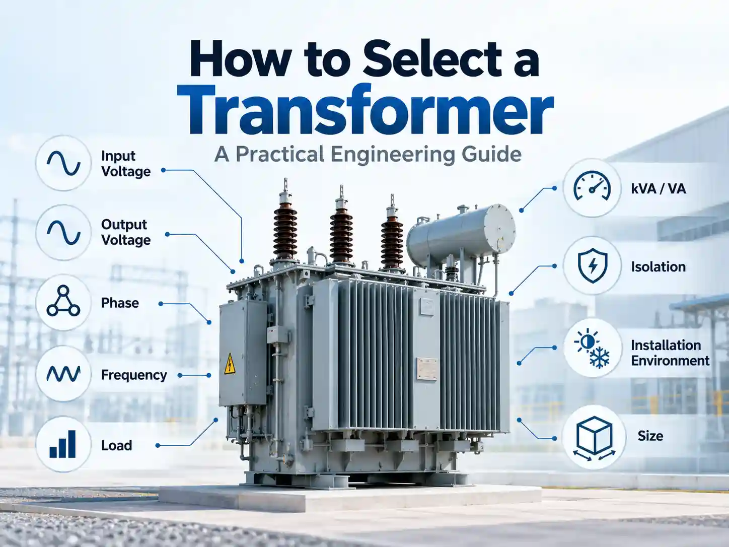
Selection checklist:
-
Rated power (VA or MVA) and whether step up, step down, or isolation
-
Primary and secondary voltages; number of output taps
-
Frequency: 50 Hz, 60 Hz, 400 Hz, or higher for switch-mode applications
-
Cooling type and thermal class; ambient temperature; altitude derating
-
Phase: single-phase or three phase; winding configuration (delta, star)
-
Environment: indoor, outdoor, medical, industrial; vibration; humidity
-
Applicable certifications and standards: IEC 60601, IEC 62368-1, IEC 61000, UL/EN safety
DOREXS supports custom transformer work from specification and simulation through prototype, certification guidance, and volume production. This includes industrial automation, medical devices, and high-reliability electronics where DC current isolation, low leakage, and noise suppression are non-negotiable. In our next article, we will cover advanced EMI filter integration techniques for transformer-coupled power supplies.
How to Select a Transformer: A Practical Engineering Guide