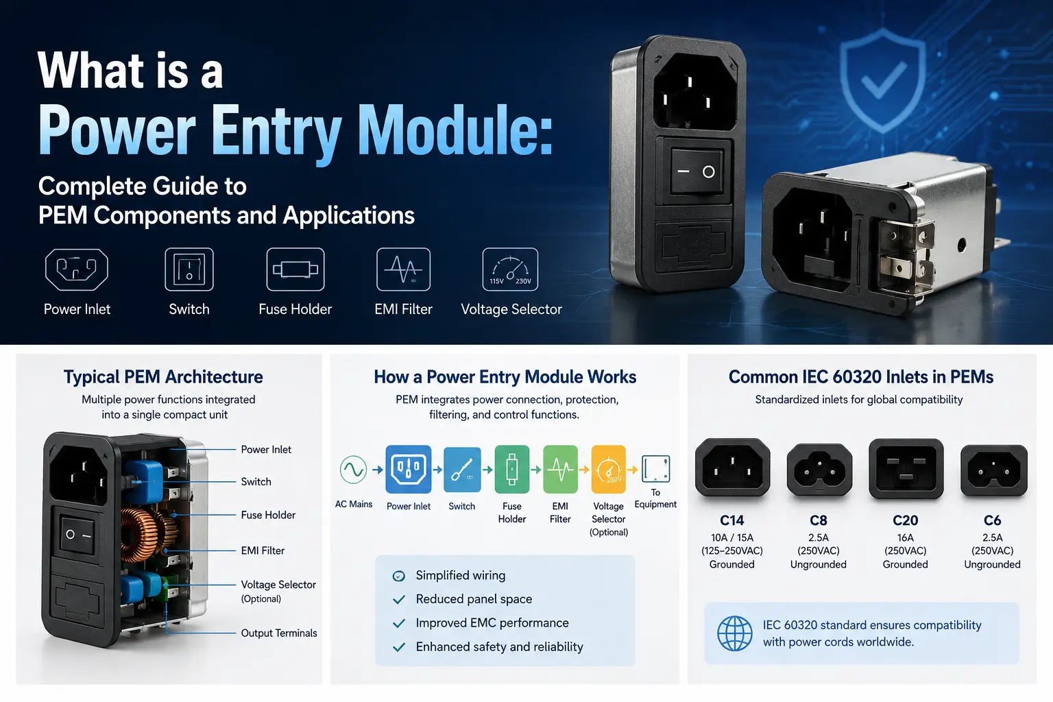
What Is an EMC Filter? How It Works, Types and Selection Guide
So, what is an EMC filter?
An EMC filter is an electrical filtering network designed to reduce unwanted electromagnetic interference conducted through power or signal lines while allowing the required AC or DC power to pass. In power applications, it normally uses inductors, common-mode chokes, X capacitors, and Y capacitors to attenuate high-frequency noise.
For engineering and procurement teams building medical devices, industrial automation equipment, consumer electronics, or home appliances, understanding EMC filters is essential when stable power, EMC compliance, and reliable product operation are required. This article explains how EMC filters work, the main filter types, common-mode and differential-mode noise, key components, installation practices, applicable EMC standards, typical applications, and how to choose the correct filter for a given design.
EMC filters are widely used in industrial automation, VFDs, servo systems, medical equipment, power supplies, EV charging equipment, renewable energy systems, communication equipment and other electronic devices that must operate reliably in a shared electromagnetic environment. An EMC filter should not be considered a complete EMC solution by itself, because filter performance depends on the noise source, frequency, source and load impedance, grounding, shielding, cable routing, installation and the overall equipment design.
Key Takeaways
-
An EMC filter primarily reduces unwanted conducted electromagnetic interference on electrical lines.
-
EMC filters and EMI filters often refer to the same type of filtering product in practical power-electronics applications.
-
Common-mode and differential-mode noise require different filtering mechanisms.
-
Typical EMC filters use common-mode chokes, inductors, X capacitors and Y capacitors.
-
Voltage, current, attenuation, leakage current, system topology and installation conditions should all be considered when selecting a filter.
-
An EMC filter can support EMC compliance, but installing a filter does not by itself guarantee that complete equipment will pass EMC testing.
What Is an EMC Filter?
An EMC filter, or electromagnetic compatibility filter, is a filtering circuit used to limit unwanted electromagnetic disturbances passing through electrical conductors.

For a typical power-line application, the basic objective is simple:
Allow the required power to pass while attenuating unwanted high-frequency electrical noise.
Most power-line EMC filters therefore behave broadly as low-pass filtering networks. DC or 50/60 Hz AC power passes through the filter with relatively low impedance, while unwanted higher-frequency currents encounter increased impedance or are diverted through capacitive paths.
An EMC filter may be installed between:
Power Source → EMC Filter → Equipment
or between a noise-generating load and the power network:
Power Network ← EMC Filter ← Noise-Generating Equipment
In practice, the filter can help in both directions. It can reduce noise leaving equipment and propagating back onto the power line, while also reducing some conducted interference entering equipment from the external electrical network.
EMC filters predominantly address conducted interference. They may indirectly affect some radiated behavior by reducing high-frequency current flowing on cables, but a power-line EMC filter is not a replacement for shielding, proper grounding, PCB layout, cable management or enclosure design.
What Does EMC Mean?
EMC stands for Electromagnetic Compatibility.
Electromagnetic compatibility describes the ability of electrical or electronic equipment to operate satisfactorily in its electromagnetic environment without producing unacceptable electromagnetic disturbances for other equipment.
This introduces two important EMC concepts:
Emissions
The equipment should not generate excessive electromagnetic interference that affects other devices. Some sources are intentional, such as radio frequency transmitters that can contribute to radio interference.
Immunity
The equipment should continue operating acceptably when exposed to electromagnetic disturbances within the requirements applicable to the product. Compliance also depends on immunity testing to verify that equipment continues operating correctly when exposed to electromagnetic disturbances.
An EMC filter is therefore one engineering tool used to improve overall electromagnetic compatibility.
It does not create EMC compliance on its own.
For example, a machine may have excellent input filtering but still experience EMC problems because of:
-
Poor protective-earth bonding
-
Long unshielded motor cables
-
High-frequency switching loops
-
Inadequate PCB layout
-
Poor cable separation
-
Shield termination problems
-
Noise coupling around the filter
-
Inadequate enclosure shielding
EMC must therefore be considered at system level.
For equipment that has already experienced EMC test problems, understanding common EMC test failures can help identify whether the problem originates from power-line conducted noise, grounding, shielding or another coupling path.
EMC Filter vs EMI Filter: Is There a Difference?
One of the most common questions is:
Is an EMC filter the same as an EMI filter?
In many power-line filtering applications, EMC filter and EMI filter are used interchangeably.
The difference is mainly one of terminology.
Electromagnetic interference (EMI) describes unwanted electromagnetic disturbances.
EMC, or electromagnetic compatibility emc, describes the broader goal of enabling equipment to operate correctly without causing unacceptable electromagnetic disturbance.
If you are unfamiliar with the basic terminology, see our guide explaining what an EMI filter is.
Therefore:
|
Term |
Main Meaning |
|---|---|
|
EMI |
Electromagnetic interference itself |
|
EMI Filter |
Filter used to suppress electromagnetic interference |
|
EMC |
Overall electromagnetic compatibility of equipment or systems |
|
EMC Filter |
Filter used as part of an EMC control strategy |
A manufacturer may therefore describe essentially the same product as:
-
EMC filter
-
EMI filter
-
EMI/RFI filter
-
RFI filter
-
Power line filter
-
Mains filter
-
Noise filter
The product name alone is not enough to determine suitability.
Engineers should instead evaluate the filter's:
-
Rated voltage
-
Rated current
-
Common-mode attenuation
-
Differential-mode attenuation
-
Insertion loss
-
Leakage current
-
Circuit topology
-
Safety requirements
-
Mechanical configuration
-
Intended application
How Does an EMC Filter Work?
A power-line EMC filter’s primary function is to suppress unwanted high-frequency interference on the line while allowing normal power to pass, using frequency-dependent impedance; in many applications, line filters are placed at the input stage to help limit conducted emissions.

Inductors oppose rapid changes in current and generally present increasing impedance as frequency rises.
Capacitors, by contrast, present decreasing impedance as frequency increases and can provide a path for high-frequency noise away from the desired power path.
Combining these components produces a network that allows normal power transmission while attenuating unwanted high-frequency energy.
For a more detailed explanation of component behavior, impedance and attenuation mechanisms, see How Does an EMC Filter Work?
A typical single-phase structure may look conceptually like:
AC Line → Filter Network → Equipment
Inside the filter:
Common-Mode Choke + X Capacitor + Y Capacitors + Additional Inductance
The actual circuit depends on the application and required attenuation.
Understanding the filter properly requires separating EMI into two important noise modes.
Common Mode Noise
Common-mode noise appears in the same general direction on multiple conductors relative to chassis or protective earth.
Typical causes include:
-
Switching-node capacitance to chassis
-
Motor winding-to-frame capacitance
-
Power semiconductor switching
-
Transformer parasitic capacitance
-
Cable-to-ground capacitance
A common-mode choke presents substantial impedance to common-mode high-frequency current while allowing the normal load current to pass.
Y capacitors may also provide a controlled high-frequency path between line conductors and protective earth.
Together, these components form an important part of common-mode noise suppression.
Differential Mode Noise
Differential-mode noise appears between power conductors.
For a single-phase AC system, this commonly means noise between:
Line ↔ Neutral
For DC systems:
DC+ ↔ DC−
In three-phase systems, differential disturbances can exist between phase conductors.
Differential-mode filtering typically uses:
-
Series inductance
-
Differential-mode inductors
-
X capacitors between conductors
-
Multi-stage LC networks
For a deeper comparison of the two interference mechanisms, read our guide to differential-mode vs common-mode noise.
A filter therefore needs an appropriate combination of CM and DM filtering according to the actual measured interference.
What Is Inside an EMC Filter?
Although EMC filters are available in many configurations, several core components are particularly common inside many EMC filters and help protect sensitive electronic components.

Common Mode Choke
A common-mode choke contains coupled windings on a magnetic core.
During normal power flow, magnetic effects associated with the load current largely compensate, allowing the required current to pass.
For common-mode interference, however, the noise currents produce magnetic flux that results in significant high-frequency impedance.
The choke can therefore strongly attenuate common-mode conducted interference without introducing excessive impedance to normal load current.
X Capacitors
X capacitors are connected between power conductors.
For example:
Line ↔ Neutral
Their main filtering role is associated with differential-mode interference.
At high frequencies, the capacitor provides a lower-impedance path that reduces differential noise appearing across the line conductors.
The capacitor type and rating must be appropriate for connection across the power line.
Y Capacitors
Y capacitors are typically connected between power conductors and protective earth or chassis.
For example:
Line → Y Capacitor → PE
and
Neutral → Y Capacitor → PE
These capacitors can significantly improve common-mode attenuation.
However, they also influence leakage current, making their selection especially important in applications such as medical equipment or systems using sensitive residual-current protection.
Increasing capacitance cannot therefore be treated as a universal method for improving filter performance.
Differential Mode Inductors
Additional series inductance may be included to increase differential-mode attenuation.
Depending on the required suppression level, filters may use:
-
Single-stage topology
-
Two-stage topology
-
Multi-stage topology
More stages can provide stronger attenuation in some conditions, but additional filter complexity does not automatically guarantee better performance in every real installation.
What Problems Can an EMC Filter Solve?
A properly selected and installed EMC filter can help address several problems.
Conducted emissions failures
Switching converters, VFDs, servo amplifiers and power supplies can inject high-frequency currents onto the AC or DC power network as conducted EMI, affecting power lines and the upstream power grid.
An input EMC filter can attenuate this noise before it reaches the external supply. For example, a suitable filter may reduce measured emissions from 58dBμV to 42dBμV.
Noise entering sensitive equipment
External switching devices may inject interference into a shared electrical network.
A filter installed at the equipment input can reduce some of this conducted noise and help protect nearby equipment connected to the same network from conducted disturbances.
Communication instability
Unstable power-line interference can degrade signal integrity and contribute to unstable behavior in PLC, industrial communication, sensor and control systems.
Filtering the relevant noise path may improve the electromagnetic environment, although signal shielding, grounding and wiring should also be evaluated.
Unexpected resets or control errors
High-frequency disturbances can sometimes contribute to controller resets, errors from nearby sensors, or unstable electronic operation.
Again, the actual coupling path should be identified rather than assuming that every problem requires a larger filter, since interference can also cause signal distortion in sensitive control or monitoring circuits.
EMC test failures
When conducted emissions exceed the applicable limit at particular frequencies, an appropriately designed EMC filter may provide the required attenuation.
The best selection normally begins with actual EMC measurement data rather than choosing a filter only from voltage and current.
Types of EMC Filters
Different electrical systems require different filter configurations.
|
EMC Filter Type |
Typical Use |
|---|---|
|
Single-phase AC equipment, power supplies and industrial electronics |
|
|
VFDs, servo drives, industrial machinery and high-power systems |
|
|
Compact equipment using IEC power connectors |
|
|
Electronic assemblies and compact power supplies |
|
|
DC power systems, battery equipment and power converters |
|
|
Shielded enclosures requiring high-frequency filtering at cable entry points |
|
|
Variable frequency drive and motor-drive systems |
|
|
Equipment requiring strict leakage-current control |
|
|
Integrated inlet, filtering, fuse and switching functions |
Selecting the correct category is only the first stage. The electrical and EMC requirements must still be matched to the application.
How to Choose an EMC Filter
Choosing an EMC filter based only on rated current is one of the most common selection mistakes, because choosing the right filter depends on several key parameters and not current alone.

For a more detailed selection process, see our EMI filter selection guide.
Engineers should consider the following factors, including performance targets and regulatory compliance.
1. Rated Voltage
The filter must be designed for the system's actual maximum operating voltage.
Examples include:
-
115 VAC
-
230/250 VAC
-
380/400 VAC
-
440/480 VAC
-
DC power systems
The system topology should also be identified correctly.
2. Rated Current
The EMC filter's current rating should accommodate the actual continuous operating current under expected thermal conditions.
Also consider:
-
Inrush current
-
Peak load conditions
-
Ambient temperature
-
Cooling
-
Duty cycle
-
Manufacturer derating requirements
Selecting a current rating that is too low may cause excessive heating or reliability problems.
3. Single Phase or Three Phase
A single-phase AC system and a three-phase industrial power system require different filter topologies.
For three-phase applications, determine whether the system uses:
-
Three-phase three-wire
-
Three-phase four-wire
-
Neutral conductor
-
Protective earth
-
Delta configuration
-
Wye/star configuration
If you are comparing the two basic architectures, see three-phase EMI filters vs single-phase EMI filters.
4. Noise Frequency
The filter must provide useful attenuation across the frequency range where the EMC problem actually occurs.
For example, if an EMC test shows excessive conducted noise around a particular switching harmonic, engineers should evaluate filter performance around that problem area rather than relying only on a general marketing statement such as "high attenuation."
5. Common Mode vs Differential Mode Noise
Determine whether the dominant interference is:
Common mode, differential mode, or a combination of both.
This can significantly affect the required filter topology.
6. Insertion Loss
Insertion loss curves provide useful information about the attenuation characteristics of a filter.
However, actual installed performance can differ from laboratory curves because real source and load impedances are rarely identical to standardized test conditions.
The filter should therefore be evaluated as part of the complete system whenever possible.
7. Leakage Current
Line-to-earth capacitance contributes to leakage current.
This becomes especially important for:
-
Medical equipment
-
Laboratory equipment
-
Portable equipment
-
Systems using RCD/RCCB protection
-
Multiple filters connected to the same supply
Low-leakage requirements may require a different filter topology from a general industrial design.
8. Mechanical Requirements
Consider:
-
Available installation space
-
Terminal type
-
Bolt connection
-
Terminal block
-
Wire lead
-
DIN rail mounting
-
PCB mounting
-
Panel mounting
-
Busbar connection
-
Cooling and enclosure layout
A filter that performs well electrically but cannot be integrated correctly into the equipment is not a suitable solution.
Where Should an EMC Filter Be Installed?
For a power-line filter, installation is often as important as filter selection.
In many applications, the filter should be installed as close as practical to the equipment power-entry point.
A common layout is:
Mains Entry → EMC Filter → Internal Equipment
This arrangement helps prevent unfiltered conductors inside the enclosure from coupling interference around the filter.
The filter housing should normally have a short, low-impedance connection to the chassis or protective-earth structure according to the manufacturer's installation requirements.
The input and output wiring should also be physically separated where possible.
For detailed installation practices, see How to Install an EMI Filter.
Common EMC Filter Installation Mistakes
Even a high-performance filter may provide disappointing results when installed incorrectly.
Long wiring between power entry and filter
Long unfiltered conductors can behave as coupling paths or antennas.
Keep the connection between power entry and filter short.
Input and output cables routed together
If dirty-side and clean-side conductors run parallel or are bundled together, high-frequency noise can couple around the filter.
Separate them physically.
Poor chassis bonding
High-frequency performance depends strongly on connection impedance.
A long grounding wire may have significantly higher high-frequency impedance than a short, broad chassis connection.
Grounding can significantly affect real filter performance. See our practical guide explaining how grounding impacts EMI performance.
Installing the filter too far from the enclosure entry
This gives noise additional opportunities to couple into other wiring before it reaches the filter.
Assuming the filter solves every EMC problem
Power-line filtering does not replace:
-
Cable shielding
-
Chassis bonding
-
Proper PCB layout
-
Grounding
-
ferrite cores
-
Shield termination
-
Reduction of switching-loop area
-
Motor cable management
Successful EMC engineering usually requires several measures working together.
EMC Filters and EMC Standards
The EMC standard applicable to equipment depends on the product category, electromagnetic environment and target market.
For industrial equipment, standards may include product-specific requirements or generic standards where no dedicated product or product-family standard applies.
Examples include:
CISPR 11
CISPR 11 covers radio-frequency disturbance characteristics, limits and measurement methods for industrial, scientific and medical equipment.
IEC 61000-6-4
IEC 61000-6-4 provides generic emission requirements for equipment intended for industrial environments where no applicable dedicated product or product-family emission standard exists.
IEC 61000-6-2
IEC 61000-6-2 addresses generic immunity requirements for equipment intended for industrial environments where no relevant dedicated product standard applies.
CISPR 32
CISPR 32 addresses emission requirements for multimedia equipment.
Other applications such as motor drives, medical devices, EV charging equipment or household appliances may be subject to different product-specific standards.
For more information about DOREXS product compliance and available approvals, visit our Certifications and Standards resource page.
An EMC filter should therefore be selected according to the actual equipment standard and measured EMC problem, rather than assuming one standard applies universally.
Most importantly:
An EMC filter itself does not make an entire machine EMC compliant.
Compliance is determined at equipment or system level.
Typical EMC Filter Applications
EMC filters are used across a wide range of electrical and electronic equipment.
Industrial Automation
Industrial automation systems contain many potential EMI sources, including:
-
Switching power supplies
-
PLC systems
-
Servo drives
-
Motor controllers
-
Relays and contactors
-
Industrial computers
-
Communication networks
Input EMC filtering can help prevent switching noise from propagating through shared power systems.
Variable Frequency Drives
VFDs generate fast switching voltage edges that can produce significant common-mode and differential-mode interference.
A suitable three-phase or VFD EMC filter may be installed at the drive input as part of a broader EMC strategy. IEC 61800-3 sets EMC requirements for adjustable speed drives and is commonly relevant in VFD applications. In many systems, engineers pair this with targeted emi filter solutions around frequency converters to reduce conducted noise and support compliance.
Motor cable shielding, grounding, cable length and drive installation remain critical. Output-side protection can also help limit stress on motor insulation from high dv/dt switching.
Servo Systems
Servo amplifiers use high-speed power switching and operate near sensitive encoder and communication circuits.
Appropriate power-line filtering can reduce conducted interference entering or leaving the servo power system.
For more application-specific information, see EMI Filters for Servo Drives.
Medical Equipment
Medical equipment may require strong EMI attenuation while also controlling leakage current.
This creates an important filter-design trade-off because increasing line-to-earth capacitance may improve common-mode attenuation while increasing leakage current.
Low-leakage EMC filters are therefore often required.
EV Charging and Renewable Energy
EV charging equipment, solar inverters, energy-storage converters and other power-electronic systems contain high-frequency switching stages.
AC and DC power paths may both require EMC analysis depending on the system architecture. Better filtering can also reduce stress on connected equipment, improve system performance, and lower the risk of transformer failures in larger renewable installations such as wind turbines to help ensure reliable operation.
Renewable-energy systems may present different interference paths because of inverter switching, DC buses, long cables and grid interfaces. More information is available in our EMI Filters for Renewable Energy application guide.
Communication and Data Equipment
Sensitive data and communication equipment can be affected by electrical noise entering through the power supply.
Power-entry filtering can help reduce conducted disturbances while other measures manage signal-line and radiated interference.
CNC Machines and Robotics
CNC systems and robots commonly combine:
-
Servo drives
-
VFDs
-
PLCs
-
Switching power supplies
-
Encoders
-
Industrial communication
Controlling interference at the power input can be one part of maintaining a stable electromagnetic environment.
DOREXS EMC Filter Solutions
DOREXS manufactures EMI filter solutions for equipment manufacturers, system integrators and industrial applications.
Available filter categories include:
-
Single Phase EMI/EMC Filters
-
Three Phase EMI/EMC Filters
-
IEC Inlet Filters
-
PCB EMI Filters
-
DC EMI Filters
-
Feedthrough Filters
-
VFD Filters
-
Medical Low-Leakage Filters
-
Power Entry Modules
-
Custom EMI/EMC Filters
You can also browse the complete DOREXS EMI filter product range according to power system, equipment architecture and application requirements.
Standard filters can be used where existing voltage, current, attenuation, leakage-current and mechanical specifications match the equipment requirements.
For applications where a standard filter does not meet the electrical, EMC or installation requirements, a custom EMI filter may be considered.
DOREXS can evaluate project requirements based on information such as:
Operating Voltage + Maximum Current + Power System + Equipment Type + EMC Problem Frequency + Leakage Current Requirement + Installation Space + Target EMC Standard
EMC test data is particularly useful.
If equipment has already failed conducted-emissions testing, providing the test report or problem frequencies can help engineers evaluate the amount and type of attenuation required more effectively than selecting a filter from current rating alone.
Frequently Asked Questions
What does an EMC filter do?
An EMC filter attenuates unwanted electromagnetic interference traveling through electrical conductors while allowing the required power or signal to pass. Power-line EMC filters are mainly used to control conducted electromagnetic noise.
Is an EMC filter the same as an EMI filter?
In many power-line applications, the terms EMC filter and EMI filter are used interchangeably. EMI describes electromagnetic interference, while EMC describes the broader goal of electromagnetic compatibility. Actual filter selection should be based on electrical and attenuation characteristics rather than terminology alone.
How does an EMC filter work?
An EMC filter typically combines inductors and capacitors. Inductive components create high impedance to unwanted high-frequency currents, while capacitors provide controlled low-impedance paths for high-frequency noise. The combination attenuates EMI while allowing the required AC or DC power to pass.
What is the difference between common-mode and differential-mode noise?
Common-mode noise appears on multiple conductors relative to ground or chassis, while differential-mode noise exists between power conductors. Common-mode chokes and Y capacitors are commonly used for CM suppression, while X capacitors and differential inductance help control DM noise.
Where should an EMC filter be installed?
A power-line EMC filter should generally be installed close to the equipment power-entry point, with short wiring, effective chassis bonding and physical separation between the unfiltered and filtered sides.
Can an EMC filter help equipment pass EMC testing?
A properly selected and installed filter can significantly reduce conducted emissions and may help equipment meet applicable EMC limits. Final compliance, however, depends on the complete system, including grounding, shielding, PCB layout, cable routing and enclosure design.
How do I choose the correct EMC filter?
Consider rated voltage, continuous current, phase configuration, noise frequency, common-mode and differential-mode attenuation, insertion loss, leakage-current requirements, mechanical dimensions and the applicable EMC standard.
Do VFDs need EMC filters?
VFD systems frequently generate conducted interference because of high-speed semiconductor switching. Depending on the drive design, installation and applicable EMC requirements, a properly selected three-phase or dedicated VFD input EMC filter can improve system performance and reduce issues such as voltage spikes affecting connected equipment, while in output applications sine wave filters may also be used as part of the overall EMC solution.
Conclusion
So, what is an EMC filter?
An EMC filter is an electrical filtering network designed to reduce unwanted conducted electromagnetic interference while allowing the required AC or DC power to pass.
Most power-line EMC filters use combinations of:
Common-Mode Chokes + Differential Inductance + X Capacitors + Y Capacitors
to attenuate common-mode and differential-mode interference.
However, effective EMC filtering requires more than simply installing a filter.
The correct solution depends on:
Voltage + Current + Noise Mode + Problem Frequency + Leakage Current + Source/Load Conditions + Grounding + Installation + Applicable EMC Standard
For OEM equipment manufacturers, the most reliable approach is to identify the actual interference problem first and then select or design the filter around measured system requirements.
Need Help Selecting an EMC Filter?
If you are developing industrial equipment, VFD systems, servo equipment, medical electronics, EV charging equipment, communication systems or other power-electronic products, DOREXS can support EMC filter selection and customized filtering solutions.
Send us:
Operating Voltage
Maximum Current
Power System
Equipment Type
EMC Test Problem / Frequency
Leakage Current Requirement
Installation Space
Target EMC Standard
DOREXS engineers can evaluate the application and recommend a suitable standard or customized EMI/EMC filtering solution.
Explore DOREXS EMI/EMC Filters →
What Is an RFI Filter? How It Works, Applications, and Selection Guide