
How to Suppress EMI in Switching Power Supplies
Understand the electromagnetic interference suppression technology of these switching power supplies to get twice the result with half the effort.
Electromagnetic compatibility (EMC) refers to the ability of electronic equipment or systems to operate normally in their electromagnetic environment without causing intolerable electromagnetic disturbance to anything in the environment. It includes two aspects: electromagnetic interference (EMI) and electromagnetic sensitivity (EMS). EMI refers to the interference emitted by electrical products. EMS refers to the ability of electrical products to resist electromagnetic interference. A device with good electromagnetic compatibility should neither be affected by surrounding electromagnetic noise nor cause electromagnetic interference to the surrounding environment. The three elements of electromagnetic interference are interference sources, coupling channels and sensitive bodies. Suppressing the interference generated by switching power supplies is of great significance to ensure the normal and stable operation of electronic systems. The suppression technology of electromagnetic interference mainly includes weakening the energy of interference, isolating and weakening the noise coupling path and improving the equipment's resistance to electromagnetic disturbance. This article analyzes the causes of electromagnetic interference in switching power supplies, and introduces the electromagnetic interference suppression technology and design methods of switching power supplies.
The generation of electromagnetic interference in switching power supply
The switching power supply usually rectifies the power frequency alternating current into direct current, and then converts it into high frequency through the control of the switching tube, and then outputs it through the rectification and filtering circuit to obtain a stable DC voltage. Power frequency rectification and filtering uses large-capacity capacitors to charge and discharge, switching tubes are turned on and off at high frequencies, and reverse recovery of output rectifier diodes produces extremely high di/dt and du/dt, forming a strong surge current. And peak voltage, which is the most basic cause of electromagnetic interference in switching power supplies. In addition, the driving waveform of the switching tube and the drain-source waveform of the MOSFET are all periodic waves close to the rectangular wave shape. Therefore, its frequency is at the MHz level, and these high-frequency signals cause interference to the basic signals of the switching power supply, especially the signals of the control circuit,, and propagated through power lines, ground wires, air, etc., may cause interference to surrounding electronic equipment and communication systems, affecting their normal operation.Here are the causes of interference.
Harmonic interference of input rectifier circuit
The input end of the switching power supply usually uses a bridge rectifier and capacitor filter circuit. The rectifier bridge can only be turned on when the pulsating voltage exceeds the voltage on the input filter capacitor, and the current is input from the mains power supply and charges the filter capacitor. Once the voltage on the filter capacitor is higher than the instantaneous voltage of the mains power supply, the rectifier is cut off. Therefore, the current input to the circuit is pulsed and has abundant high-efficiency harmonic currents. This is because of the nonlinear characteristics of the rectifier circuit, and the current on the AC side of the rectifier bridge is severely distorted.
The harmonic order on the DC side is n times. Therefore, the high-frequency harmonic current on the DC side of the rectifier circuit not only causes the circuit to generate power and increases the reactive power of the circuit, but also high-frequency harmonics will cause conduction interference and radiation interference along the transmission line.
Interference caused by switching circuits
The switching circuit plays a key role in the switching power supply and is also one of the main sources of interference. The switching tube load is the primary coil of the high-frequency transformer, which is an inductive load. At the moment of turn-on, the primary coil generates a large inrush current, and a high surge peak voltage appears at both ends of the primary coil; at the moment of turn-off, part of the energy does not flow from the primary coil due to the leakage flux of the primary coil. Transmitted to the secondary coil, this part of the energy stored in the inductor will form an attenuated oscillation with a peak with the capacitance and resistance in the collector circuit, which will be superimposed on the turn-off voltage to form a turn-off voltage spike. If the amplitude of the spike is high enough, it is very likely that the switch tube will be broken down.
Measures to Suppress Electromagnetic Interference
There are two forms of electromagnetic interference in switching power supplies: common mode interference and differential mode interference. According to the electromagnetic interference sources analyzed previously, combined with their coupling paths, interference can be suppressed from several aspects such as EMI filters, absorption circuits, grounding and shielding, and the electromagnetic interference can be attenuated to within the allowable limit.In order to effectively suppress EMI problems in switching power supplies, some common suppression methods can be adopted:
-
Filter design: Add suitable filters (capacitor filter, inductor filter, LC filter, etc.) to the input and output ends of the switching power supply.
-
Ground wire design: Correct ground wire connection improves the anti-interference ability of the system
-
Shielding design: Use shielding materials to wrap key parts
-
Use magnetic materials: Use magnetic materials (ferrite, nickel-zinc ferrite, etc.) around the transformer and inductor of the switching power supply.
-
Spectrum analysis and optimization: Through spectrum analysis, we can understand the main frequencies and harmonic components generated in the switching power supply, optimize the circuit design in a targeted manner, and reduce the EMI level in specific frequency bands.
AC input EMI filter

Filtering is a method of suppressing conducted interference. Connecting a filter to the input end of the power supply can suppress the noise from the power grid from harming the power supply itself. It can also suppress the interference generated by the switching power supply and fed back to the power grid. As an important unit for suppressing conducted interference on power lines, power filters play an extremely important role in the electromagnetic compatibility design of equipment or systems. The power incoming end usually uses an EMI filter circuit as shown in Figure 1. This circuit can effectively suppress low-frequency differential mode harassment and high-frequency common mode harassment at the input end of the AC power supply. In the circuit, the differential mode capacitors Cx1, Cx2 (also called . The common-mode capacitors Cy1 and Cy2 (also called Y capacitors) with the intermediate connection connected to ground are used to short-circuit the common-mode noise current, and the value range is usually C1=C2 # 2 200 pF. The suppression inductors L1 and L2 are usually 100~130H. The common mode choke L is composed of two identical coils wound on a magnetic core in the same direction. The inductance L# is usually required to be 15~25 mH. When the load current flows through the common mode choke, the magnetic lines of force generated by the coils connected in series on the live line and the magnetic lines of force generated by the coils connected in series on the neutral line are in opposite directions, and they cancel each other out in the magnetic core. Therefore, the core will not saturate even at large load currents. As for the common-mode interference current, the magnetic fields generated by the two coils are in the same direction and will exhibit a large inductance, thus attenuating the common-mode interference signal.
The size of switching power supplies is getting smaller and smaller, and the power density is getting larger and larger. EMI/EMC issues have become a key factor in the stability of switching power supplies, and they have attracted more and more attention. There are many electromagnetic compatibility control strategies and control technology solutions for switching power supplies, such as suppression of interference transmission channels, separation of space, separation of time, frequency management, electrical isolation, etc. In the design of switching power supplies, only by comprehensively applying various electromagnetic interference suppression technologies can the electromagnetic compatibility of switching power supplies be effectively improved and truly meet the needs of various occasions.
DOREXS EMI SOLUTIONS
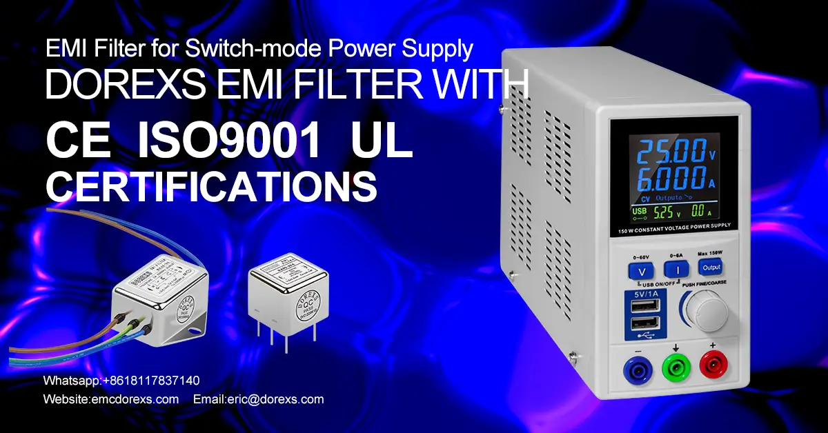
DOREXS offers EMI filters for different applications, from one phase or three phase EMI/EMC filters with IEC socket, power entry filter and chassis mounting filters. DOREXS also offer quality medical-grade EMI filters.
Find out more about DOREXS connectivity solutions, CONTACT US NOW.
EMI Filter Design
Solution for EMC Problem of EV AC Charging Pole



