
Three Phase EMI Filter Design
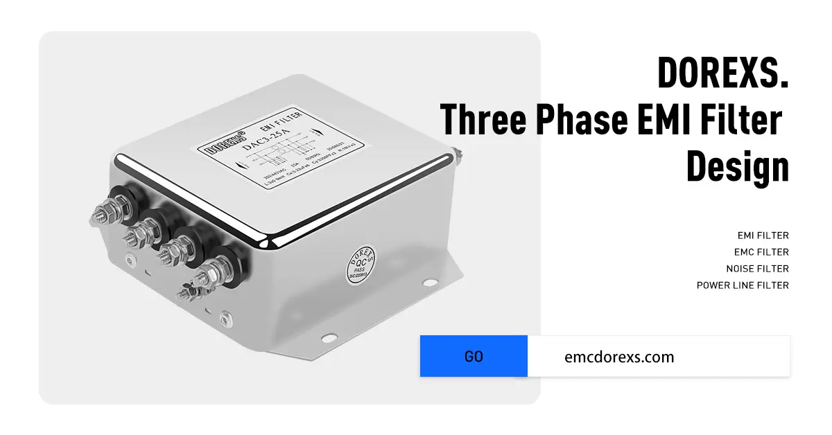
With the rapid development of modern power electronics technology, the problem of electromagnetic interference (EMI) is becoming increasingly serious. As an effective method to ensure the normal operation of high-power electronic equipment and meet the requirements of electromagnetic compatibility (EMC), three-phase EMI filter circuits are widely used in high-power electronic products and industrial systems. CE certification is crucial for ensuring these products meet safety and efficacy criteria in the marketplace.
This article will explore the principle and parameter design method of three-phase EMI filter circuits to provide a reference for research and application in related fields. Additionally, it will introduce the concept of different configurations, specifically Delta and WYE configurations, in three-phase power systems, which are essential for enhancing power distribution and ensuring optimal equipment performance.
This article will explore the principle and parameter design method of three-phase EMI filter circuits to provide a reference for research and application in related fields. Additionally, it will introduce the concept of different configurations, specifically Delta and WYE configurations, in three-phase power systems, which are essential for enhancing power distribution and ensuring optimal equipment performance.
Introduction to EMI Filters

Electromagnetic interference (EMI) is a prevalent problem in electronic devices, often causing equipment failure or even damage. To combat this, EMI filters, including three-phase filters, are designed to mitigate EMI in power lines and other devices. These filters are essential to ensure compliance with strict regulations and prevent interference with other nearby devices.
3-phase EMI filters work by suppressing both common-mode noise and differential-mode noise that are prevalent in three-phase power systems. Common-mode inductors are often used in these filters to effectively reduce common-mode noise. The selection of capacitors and inductors is essential to designing an effective EMI filter, as these components play a vital role in the performance of the filter.
These filters are used in various industries such as medical, industrial, and robotics, and they are designed to handle high-frequency and high-power applications. This makes them indispensable in three-phase power systems. The design of EMI filters requires careful consideration of factors such as weight, size, and connection options to ensure optimal performance.
An example of an EMI filter is a three-phase filter, which is specifically designed to reduce EMI in three-phase power systems. By adopting these filters, industries can ensure that their electronic devices operate reliably, maintain regulatory compliance, and improve overall system performance.
3-phase EMI filters work by suppressing both common-mode noise and differential-mode noise that are prevalent in three-phase power systems. Common-mode inductors are often used in these filters to effectively reduce common-mode noise. The selection of capacitors and inductors is essential to designing an effective EMI filter, as these components play a vital role in the performance of the filter.
These filters are used in various industries such as medical, industrial, and robotics, and they are designed to handle high-frequency and high-power applications. This makes them indispensable in three-phase power systems. The design of EMI filters requires careful consideration of factors such as weight, size, and connection options to ensure optimal performance.
An example of an EMI filter is a three-phase filter, which is specifically designed to reduce EMI in three-phase power systems. By adopting these filters, industries can ensure that their electronic devices operate reliably, maintain regulatory compliance, and improve overall system performance.
Principle of Three Phase EMI Filter Circuits
1. Filtering Principle
Three phase EMI filter circuits are primarily used to suppress electromagnetic interference on both the power supply side and the load side. Their filtering principle involves suppressing or attenuating EMI through inductance (L) and capacitance (C) components, ensuring the stability of the power system and the normal operation of electronic equipment. In a three-phase system, the filter needs to withstand the harmonic components of the three-phase voltage, necessitating the design of appropriate inductance and capacitance parameters to achieve optimal filtering.
2. Circuit Composition
The three-phase EMI filter circuit mainly consists of inductance, capacitance, and resistance components. Inductance is primarily used to suppress high-frequency harmonics, capacitance is used to suppress low-frequency harmonics, and resistance is used to limit the current after filtering. In practical applications, the selection and combination of inductance, capacitance, and resistance significantly influence the filtering effect, especially in handling different current ratings.
In a Delta configuration, the system consists of three phases without a neutral, which optimizes power generation and affects filter functionality. The difference between Delta and WYE configurations lies in the presence of a neutral terminal in WYE, impacting filter design and performance, particularly in managing common-mode inductors and ensuring proper current balancing within the system.
In a Delta configuration, the system consists of three phases without a neutral, which optimizes power generation and affects filter functionality. The difference between Delta and WYE configurations lies in the presence of a neutral terminal in WYE, impacting filter design and performance, particularly in managing common-mode inductors and ensuring proper current balancing within the system.

Defining Design Requirements
- Voltage and Current Levels: Determine the voltage and current that the filter needs to handle.
- Frequency Range: Identify the frequency range of EMI that needs to be filtered out.
- Attenuation Requirements: Specify the attenuation level required within a specific frequency range.
Selecting Filter Topology
Common EMI filter topologies include:
- LC Filter: Consists of an inductor (L) and a capacitor (C), suitable for interference in the low to medium frequency range.
- π-Type Filter: Consists of two capacitors and one inductor, suitable for interference over a wider frequency band.
- T-Type Filter: Consists of two inductors and one capacitor, also suitable for a wider frequency band.
Parameter Design of Three-Phase EMI Filter Circuits

1. Inductor Parameter Design
Inductance Selection: Larger inductance values offer better filtering effects, but also increase the size and weight of the inductor. The appropriate inductance should be selected based on the actual application scenario and EMI suppression requirements. Figures can be used to illustrate the design parameters and their impact on performance. Influence of Inductor Parasitic Parameters: The parasitic resistance and capacitance of the inductor affect the filtering effect. Select inductors with low resistance and low capacitance to improve the filtering performance.
2. Capacitor Parameter Design
Capacitance Selection: It is important to select the right capacitance values for effective filtering. Larger capacitance values offer better filtering effects, but also increase the volume and weight of the capacitor. Choose the appropriate capacitance based on the actual application scenario and EMI suppression requirements. Influence of Capacitor Parasitic Parameters: The parasitic resistance and inductance of the capacitor affect the filtering effect. Select capacitors with low resistance and low inductance to enhance the filtering performance. Preventing noise from interfering with the operation of electronic appliances is crucial for maintaining device functionality.
3. Resistor Parameter DesignResistor Value Selection: Larger resistance values result in smaller current after filtering, but also increase the heat generated by the resistor. Select the appropriate resistance value based on the actual application scenario and EMI suppression requirements. Influence of Resistor Parasitic Parameters: The parasitic inductance and capacitance of the resistor affect the filtering effect. Select resistors with low inductance and low capacitance to improve the filtering performance.
2. Capacitor Parameter Design
Capacitance Selection: It is important to select the right capacitance values for effective filtering. Larger capacitance values offer better filtering effects, but also increase the volume and weight of the capacitor. Choose the appropriate capacitance based on the actual application scenario and EMI suppression requirements. Influence of Capacitor Parasitic Parameters: The parasitic resistance and inductance of the capacitor affect the filtering effect. Select capacitors with low resistance and low inductance to enhance the filtering performance. Preventing noise from interfering with the operation of electronic appliances is crucial for maintaining device functionality.
3. Resistor Parameter DesignResistor Value Selection: Larger resistance values result in smaller current after filtering, but also increase the heat generated by the resistor. Select the appropriate resistance value based on the actual application scenario and EMI suppression requirements. Influence of Resistor Parasitic Parameters: The parasitic inductance and capacitance of the resistor affect the filtering effect. Select resistors with low inductance and low capacitance to improve the filtering performance.
Considering Common Mode and Differential Mode Filtering
Common Mode Interference: Affects all three-phase wires. A common method to suppress this is using a common mode choke. Line filters, particularly three-phase EMI filters, are widely used across various industries, especially by equipment manufacturers involved in industrial machinery, to ensure electromagnetic compatibility (EMC) and reduce high-frequency noise.
Differential Mode Interference: Affects the phase lines. A common method to suppress this is using a differential mode capacitor, connected between phase lines. Three-phase EMI filters are essential for effectively managing noise in high-power applications, such as industrial machinery and medical devices, which demand more power than single-phase supplies can provide.
Differential Mode Interference: Affects the phase lines. A common method to suppress this is using a differential mode capacitor, connected between phase lines. Three-phase EMI filters are essential for effectively managing noise in high-power applications, such as industrial machinery and medical devices, which demand more power than single-phase supplies can provide.
Circuit Debugging and Optimization
Debugging Method: Circuit debugging includes component parameter measurement and filtering effect testing. During the debugging process, optimize the parameters of inductance, capacitance, and resistance to achieve better filtering results while also optimizing space and cost in the design process. Optimization Strategy: For different application scenarios, adopt the following optimization strategies:
- Adjust the parameters of inductance, capacitance, and resistance to improve filtering effects.
- Use a multi-stage filter combination to enhance the filter's suppression ability.
- Use a composite filter, such as combining LC and RC filters, to increase the filter's adaptability.
Additionally, EMC testing for printed circuit boards (PCBs) is crucial to ensure that the filters meet regulatory compliance and effectively mitigate electromagnetically-induced interference.
Example Design
Suppose we need to design a three-phase EMI filter that operates in a 400V, 50Hz power supply system, with the goal of filtering out interference above 150kHz across different phases, considering the complexities and requirements of filtering noise.
- Select a π-type power line filter topology.
- Determine the parameters of the common-mode choke and differential-mode capacitor, ensuring they are suitable for industrial machinery applications.
- Calculate and select appropriate inductance and capacitance values, taking into account the different rated currents available for the GTX three-phase family of filters.
In the actual design process, adjustments and optimizations may be required based on specific circumstances, including the presence of an additional phase which complicates the filtering process. Below is a simplified design example:
The importance of power line filters in minimizing electromagnetic interference cannot be overstated. Selecting the right product tailored to specific customer needs is crucial for achieving effective performance. Advancements in nanocrystalline amorphous metal technology allow for the size and weight of line filters to be reduced while maintaining overall performance.
Specific examples, as shown in the tables and figures, illustrate key points about line filter specifications. Compliance with specific emission standards for EMI/RFI filters is essential. High-frequency switching techniques employed in circuits generate significant harmonic noise, necessitating careful design considerations.
Voltage specifications in delta and wye configurations of three-phase power systems typically differ. Delta systems specify the phase-to-phase voltage, while wye systems account for phase-to-neutral voltage. The WYE configuration includes a neutral wire, which is crucial for powering auxiliary circuits and ensuring proper filter function in EMI power line filters.
The importance of power line filters in minimizing electromagnetic interference cannot be overstated. Selecting the right product tailored to specific customer needs is crucial for achieving effective performance. Advancements in nanocrystalline amorphous metal technology allow for the size and weight of line filters to be reduced while maintaining overall performance.
Specific examples, as shown in the tables and figures, illustrate key points about line filter specifications. Compliance with specific emission standards for EMI/RFI filters is essential. High-frequency switching techniques employed in circuits generate significant harmonic noise, necessitating careful design considerations.
Voltage specifications in delta and wye configurations of three-phase power systems typically differ. Delta systems specify the phase-to-phase voltage, while wye systems account for phase-to-neutral voltage. The WYE configuration includes a neutral wire, which is crucial for powering auxiliary circuits and ensuring proper filter function in EMI power line filters.
Component Selection:
- Common mode inductor (Lcm): 2 mH
- Differential mode capacitor (Cd): 4.7 µF
- Common mode capacitor (Ccm): 1 µF
Using the above optimization strategy, the three-phase EMI filter circuit has been verified through practical application to have good electromagnetic interference suppression effects, effectively improving the product’s reliability and stability. The DOREXS three-phase family of filters offers rated currents ranging from 30 to 60 A, providing a space-efficient solution while maintaining high performance. Additionally, advancements in nanocrystalline amorphous metal technology have allowed for the size and weight of line filters to be reduced, enhancing design flexibility for power supply systems.
This article elaborates on the principle and parameter design method of the three-phase EMI filter circuit and discusses the circuit debugging and optimization strategy. With the increasing prominence of electromagnetic interference problems, three-phase EMI filter circuits will be utilized in more fields in the future!
This article elaborates on the principle and parameter design method of the three-phase EMI filter circuit and discusses the circuit debugging and optimization strategy. With the increasing prominence of electromagnetic interference problems, three-phase EMI filter circuits will be utilized in more fields in the future!
EMI Filter Circuit Basics
How Does an EMI Filter Work



