
Basic Knowledge of EMI and EMI Filters
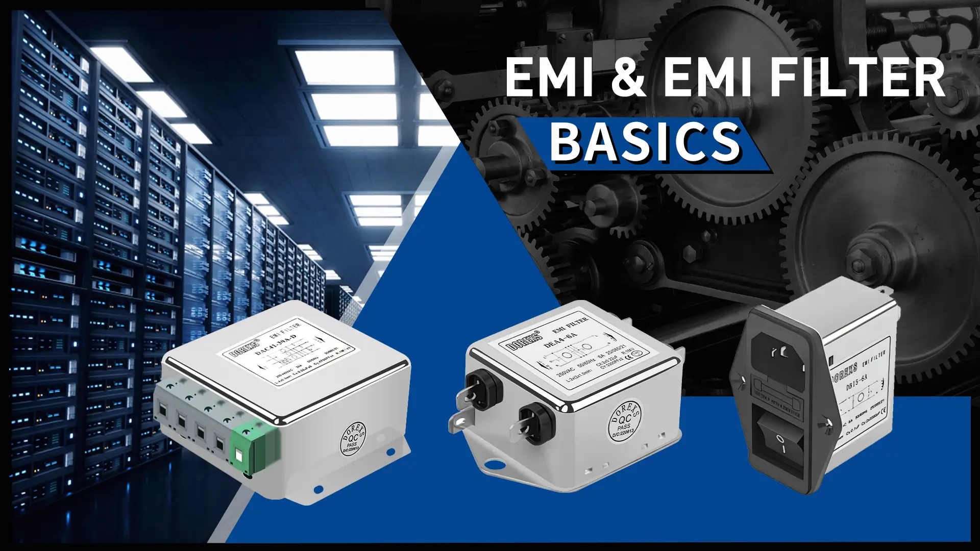
EMI (Electromagnetic Interference) refers to the harmful effects caused by electromagnetic fields in the form of radiation or conduction, which affect surrounding electronic devices. These interferences are typically transmitted as high-frequency signals into the circuits of electronic devices, disrupting their normal operation. The presence of EMI poses a significant threat to the performance, reliability, and safety of electronic devices and systems. An EMI filter, also known as an electromagnetic interference filter, is an electronic component designed to suppress electromagnetic interference and ensure signal transmission quality. It works by blocking high-frequency interference signals while allowing normal power signals to pass through. It effectively mitigates the propagation path of EMI, improving the electromagnetic compatibility (EMC) of the system.
What is EMI?
1.Definition of EMI
EMI (Electromagnetic Interference) refers to a disturbance caused by electromagnetic energy. This interference can originate from electronic devices themselves or from other electromagnetic fields in the external environment. Simply put, EMI is electromagnetic noise that disrupts the normal operation of electronic devices.
The sources of EMI can be divided into two categories: natural sources and man-made sources:
Natural Sources
Lightning: Lightning is one of the strongest natural sources of EMI, capable of generating powerful electromagnetic pulses that can cause severe interference or even damage to nearby electronic devices.
Solar Activity: Solar winds and solar flares, as part of solar activity, can produce large amounts of electromagnetic radiation, which may interfere with electronic devices on Earth.
Earth's Magnetic Field Variations: Natural changes in the Earth's magnetic field can also produce electromagnetic interference. Although this interference is usually weak, it can occasionally affect electronic devices.
Man-made Sources
Power Systems: High-voltage transmission lines, substations, and distribution networks are major sources of EMI. The current and voltage fluctuations in power systems generate electromagnetic waves, which can spread through power lines or the surrounding space and affect nearby electronic devices.
Industrial Equipment: Devices such as motors, transformers, and welding equipment generate electromagnetic interference during operation. The current and voltage changes in these devices produce electromagnetic waves that can disrupt nearby electronics.
Communication Equipment: Communication devices such as radio transmitters, mobile base stations, and radar systems emit EMI when transmitting signals. These devices typically have higher transmission power, which may cause stronger interference with other electronic devices.
Electronic Devices: Household appliances such as computers, televisions, and microwave ovens also generate EMI during operation. The current and voltage changes inside these devices produce electromagnetic waves that can interfere with nearby equipment. Additionally, some electronic devices may produce harmonic interference, which involves currents or voltages at non-fundamental frequencies generated during operation.
Transportation Systems: Electrified railways, subways, and electric vehicles also generate EMI during operation. The current and voltage fluctuations in these systems generate electromagnetic waves that can disrupt nearby electronic devices.
Lightning: Lightning is one of the strongest natural sources of EMI, capable of generating powerful electromagnetic pulses that can cause severe interference or even damage to nearby electronic devices.
Solar Activity: Solar winds and solar flares, as part of solar activity, can produce large amounts of electromagnetic radiation, which may interfere with electronic devices on Earth.
Earth's Magnetic Field Variations: Natural changes in the Earth's magnetic field can also produce electromagnetic interference. Although this interference is usually weak, it can occasionally affect electronic devices.
Man-made Sources
Power Systems: High-voltage transmission lines, substations, and distribution networks are major sources of EMI. The current and voltage fluctuations in power systems generate electromagnetic waves, which can spread through power lines or the surrounding space and affect nearby electronic devices.
Industrial Equipment: Devices such as motors, transformers, and welding equipment generate electromagnetic interference during operation. The current and voltage changes in these devices produce electromagnetic waves that can disrupt nearby electronics.
Communication Equipment: Communication devices such as radio transmitters, mobile base stations, and radar systems emit EMI when transmitting signals. These devices typically have higher transmission power, which may cause stronger interference with other electronic devices.
Electronic Devices: Household appliances such as computers, televisions, and microwave ovens also generate EMI during operation. The current and voltage changes inside these devices produce electromagnetic waves that can interfere with nearby equipment. Additionally, some electronic devices may produce harmonic interference, which involves currents or voltages at non-fundamental frequencies generated during operation.
Transportation Systems: Electrified railways, subways, and electric vehicles also generate EMI during operation. The current and voltage fluctuations in these systems generate electromagnetic waves that can disrupt nearby electronic devices.
 |
2. Classification of EMI
EMI is typically divided into two types: conducted interference and radiated interference.
Conducted Interference: This type of interference is transmitted through conductive media such as power lines, signal lines, and other wiring. When an electronic device operates, its internal current and voltage fluctuations generate electromagnetic waves that may propagate through power or signal lines, causing interference to nearby electronic devices.
Radiated Interference: This type of interference occurs through electromagnetic waves that propagate through space. As an electronic device operates, changes in its internal electric and magnetic fields generate electromagnetic radiation. These waves may interfere with nearby electronic devices, especially when their frequencies are similar.
Radiated Interference: This type of interference occurs through electromagnetic waves that propagate through space. As an electronic device operates, changes in its internal electric and magnetic fields generate electromagnetic radiation. These waves may interfere with nearby electronic devices, especially when their frequencies are similar.
3. Impact of EMI on Electronic Devices
EMI can negatively affect electronic devices in various ways, including performance degradation, data errors, and even physical damage to the device. Therefore, measures to suppress and reduce EMI must be incorporated into the design and manufacturing processes of electronic devices to ensure their proper functioning and electromagnetic compatibility (EMC).
EMI Measurement and Standards
EMI Measurement Methods
The main methods for measuring EMI (Electromagnetic Interference) include:
- Radiated Emission Testing: Measuring electromagnetic interference radiated through the air when the device is in operation.
- Conducted Emission Testing: Measuring electromagnetic interference transmitted through power lines or other connecting wires when the device is in operation.
- Radiated Immunity Testing: Evaluating the device's immunity to external electromagnetic interference.
- Conducted Immunity Testing: Evaluating the device's immunity to interference signals conducted through the power lines.
- Harmonics and Flicker Testing: For power electronic devices, measuring the harmonic components in the input current and voltage fluctuations (flicker) to assess their impact on power quality.
- Electrostatic Discharge (ESD) Testing: Simulating electrostatic discharge between the human body or devices, to test the device's tolerance and recovery ability from electrostatic shock.
Testing Equipment
Specialized testing equipment is required for EMI testing, including but not limited to:
- Spectrum Analyzer
- Scanning Receiver
- Antennas
- Signal Generator
- Oscilloscope
Testing Steps
- Determine Testing Standards: Different countries and regions have different EMI testing standards, such as FCC in the US, CE in Europe, and CISPR internationally. It is essential to identify the relevant standards before starting the test.
- Prepare Testing Equipment: Based on the testing standards, prepare the necessary testing equipment.
- Set Up the Testing Environment: Set up the testing environment in an anechoic chamber or shielded room according to the type of test (radiated or conducted).
- Connect the Device Under Test: Connect the device under test (DUT) to the testing equipment as required.
- Execute the Test: Turn on all devices and conduct the test.
- Analyze Data: Compare the test data with the standard limits to determine if the device passes the EMI test. If not, identify the sources of interference and take corrective actions.
- Generate Test Report: Generate a detailed test report, including test conditions, steps, results, and conclusions.
EMI Standards and Regulations
EMI standards and regulations ensure that electronic devices do not interfere with other equipment during operation and are resistant to external electromagnetic interference. These standards are established by international or national organizations and define clear limits and testing requirements for different applications and device types.
International EMI Standards and Regulations
CISPR (International Special Committee on Radio Interference) Standards: CISPR standards are widely adopted for EMI testing and limit regulations for various device types. Standards such as CISPR 11, CISPR 22, CISPR 24, and CISPR 35 define emission limits and testing methods for industrial, scientific, and medical (ISM) radio-frequency equipment, information technology equipment, telecommunication devices, and multimedia equipment.
IEC (International Electrotechnical Commission) Standards: The IEC 61000 series defines general electromagnetic compatibility (EMC) testing requirements, covering both immunity and emission limits. For instance, IEC 61000-3-2 sets harmonic current limits, and IEC 61000-4-6 provides testing methods for immunity against conducted disturbances.
IEC (International Electrotechnical Commission) Standards: The IEC 61000 series defines general electromagnetic compatibility (EMC) testing requirements, covering both immunity and emission limits. For instance, IEC 61000-3-2 sets harmonic current limits, and IEC 61000-4-6 provides testing methods for immunity against conducted disturbances.
Regional EMI Standards and Regulations
Europe: The EU EN series standards (such as EN 55011, EN 55022, etc.) are the European implementations of the CISPR standards.
United States: The Federal Communications Commission (FCC) has established EMC-related regulations and standards, such as FCC Part 15, which defines electromagnetic radiation limits and measurement methods for radio frequency equipment.
Japan: The Japanese Electrical Product Safety Law (DENAN Law) and VCCI (Voluntary Control Council for Interference by Information Technology Equipment) standards define EMC requirements for electronic devices.
China:China also has its own EMC standards and regulations, such as the GB/T series standards (e.g., GB/T 9254-2008, which specifies radio disturbance limits and measurement methods for information technology equipment). The CCC (China Compulsory Certification) certification system also requires electronic devices to meet relevant EMC standards.
United States: The Federal Communications Commission (FCC) has established EMC-related regulations and standards, such as FCC Part 15, which defines electromagnetic radiation limits and measurement methods for radio frequency equipment.
Japan: The Japanese Electrical Product Safety Law (DENAN Law) and VCCI (Voluntary Control Council for Interference by Information Technology Equipment) standards define EMC requirements for electronic devices.
China:China also has its own EMC standards and regulations, such as the GB/T series standards (e.g., GB/T 9254-2008, which specifies radio disturbance limits and measurement methods for information technology equipment). The CCC (China Compulsory Certification) certification system also requires electronic devices to meet relevant EMC standards.
Importance of Complying with EMI Standards and Regulations
Compliance with EMI standards and regulations is essential not only for market access but also for enhancing product reliability and competitiveness. Adopting EMC design strategies, such as shielding, grounding, and filtering, during the design phase can reduce subsequent rectification costs and help products pass certification tests quickly.
EMI standards and regulations play a crucial role in ensuring the electromagnetic compatibility of electronic devices, protecting user safety, and meeting market access requirements. Therefore, it is essential to strictly adhere to relevant standards and regulations during the design and manufacturing of electronic devices.
EMI Suppression Techniques
1. EMI Suppression at the Design Stage
EMI suppression during the design phase is the most crucial step in achieving electromagnetic compatibility (EMC). By implementing effective suppression measures in the early design stages, the costs of later modifications can be significantly reduced, and the product's reliability and compliance can be improved. Below are some EMI suppression measures that can be taken during the design phase:
- Use of EMI Filters: Adding EMI filters to power lines, signal lines, or cables, such as power line filters and radio frequency (RF) filters, can significantly reduce high-frequency noise and electromagnetic radiation.
- Application of Ferrite Cores: Using ferrite cores around cables or coils effectively absorbs high-frequency electromagnetic noise, reducing both conducted and radiated interference.
- Shielding Design: Shielding sensitive circuits and devices can block external electromagnetic radiation. Shielding can be achieved using shielded enclosures, covers, and materials. There are three types of shielding: electrostatic shielding, electromagnetic shielding, and magnetic shielding.
- Grounding Design: Ensuring proper grounding within the system by connecting all metal casings, shields, and ground wires helps reduce the impact of electromagnetic interference (EMI). Grounding design includes both PCB grounding and system grounding.
| Problem | Cause | Solution |
| PCB ground plane is not continuous | Different areas of the ground plane are not connected, resulting in return current interference | Ensure the integrity of the ground plane and increase cross-area grounding points |
| High-speed signals interfere with sensitive circuits | High-frequency signal lines are close to low-frequency or analog circuits | Isolate high-speed signals from sensitive signals |
| Ground loop interference | Improper multi-point grounding, forming a ground loop | Use single-point grounding or improve the integrity of the grounding system |
| The clock signal generates strong radiation | The clock line is too long and not shielded | Shorten the length of the clock line and add shielding |
| Power supply interference | The power line is not filtered, and the power supply noise is conducted into the circuit | Add decoupling capacitors, EMI filters or ferrite beads |
2. Type of EMI Filters
- Low-Pass Filters: These filters allow low-frequency signals to pass through while attenuating or blocking high-frequency signals.
- High-Pass Filters: These filters allow high-frequency signals to pass through while attenuating or blocking low-frequency signals.
- Band-Pass Filters: These filters allow signals within a specific frequency range to pass through while suppressing signals both below and above that frequency range.
- Band-Stop Filters: These filters suppress signals within a certain frequency band while allowing signals outside that band to pass through.
Filters play a crucial role in EMI suppression, and their type and function should be chosen based on the specific application. By optimizing filter design, conducted and radiated interference can be effectively suppressed, ensuring that devices meet EMC requirements and operate reliably in complex environments.
3. Other EMI Suppression Methods
Using Ferrite Beads: Ferrite beads are commonly used to suppress high-frequency noise in power lines, signal cables, and other conductors. They act as inductive filters that absorb EMI, reducing both conducted and radiated interference.
Using Shielding Enclosures: Shielding enclosures, such as metal covers or cases, are used to enclose sensitive electronic components, preventing external electromagnetic radiation from interfering with the device. These enclosures block EMI from entering or exiting the device, improving its EMC performance.
What is an EMI Filter?
1. Basic Principles of EMI Filters
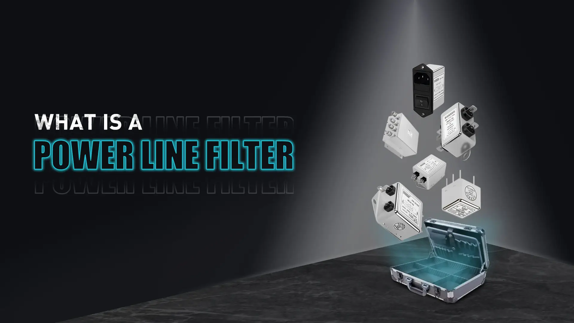
An EMI filter is an electronic component or circuit designed to suppress electromagnetic interference (EMI). Its core principle lies in frequency selectivity—allowing useful signals to pass through while blocking or attenuating unwanted interference signals, thereby enhancing the electromagnetic compatibility (EMC) of the equipment.
 |
How EMI Filters Work
Capacitors:Capacitors leverage their ability to pass high-frequency signals while blocking low-frequency signals.
They direct high-frequency interference currents from the live and neutral lines to the ground (common mode) or from the live line to the neutral line (differential mode).
Inductors:Inductors use their impedance characteristics to reflect high-frequency interference currents back to the interference source.
Ferrite for Interference Suppression:Ferrite materials can absorb interference signals within specific frequency ranges and convert them into heat.
By selecting appropriate ferrite rings or beads for specific interference frequencies and directly installing them on the cables that require filtering, electromagnetic interference can be effectively suppressed.
They direct high-frequency interference currents from the live and neutral lines to the ground (common mode) or from the live line to the neutral line (differential mode).
Inductors:Inductors use their impedance characteristics to reflect high-frequency interference currents back to the interference source.
Ferrite for Interference Suppression:Ferrite materials can absorb interference signals within specific frequency ranges and convert them into heat.
By selecting appropriate ferrite rings or beads for specific interference frequencies and directly installing them on the cables that require filtering, electromagnetic interference can be effectively suppressed.
Key Parameters of EMI Filters
- Insertion Loss
- Cut-off Frequency
- Passband Range
- Impedance Matching
- Rated Current and Voltage
- Common Mode Rejection Ratio
- Temperature Range
2. EMI filter types and structures
| Type | Structural diagram | Main purpose |
| Low-pass filter | Inductor-capacitor series or parallel structure | Suppress high-frequency conducted interference |
| High-pass filter | Capacitors in series, inductors in parallel | Suppress low-frequency signals or interference in specific frequency bands |
| π-type filter | L-C-L structure | Efficiently attenuates high-frequency conducted interference |
| Common mode filter | Common mode choke + common mode capacitor | Suppress common mode interference of power lines and improve radiation problems |
3. How to Test an EMI Filter
3.1. Visual Inspection of the Filter
When inspecting an EMI filter, the following checks should be performed:
- Appearance Check: Ensure the filter is free of damage or visible cracks.
- Connection Check: Verify that all connections are secure and there is no looseness.
- Marking Check: Confirm that the input and output terminals are clearly labeled.
If any of these issues are present, the filter may be of poor quality and is not recommended for use.
3.2. Performance Testing
Insertion Loss Test
Insertion loss is a key parameter for evaluating the performance of an EMI filter. A higher insertion loss indicates better performance.
Testing Steps:
Connect the equipment ➡ Measure the baseline ➡ Install the filter ➡ Measure the insertion loss.
Frequency Response Test
Frequency Response Test
This test determines the attenuation characteristics of the EMI filter at different frequencies.
Testing Steps:
Set the signal source ➡ Record data ➡ Analyze results.
Use the results to plot a frequency response curve, showing the filter’s attenuation and energy absorption across the frequency range.
Common Mode and Differential Mode Noise Testing
Testing Steps:
Set the signal source ➡ Record data ➡ Analyze results.
Use the results to plot a frequency response curve, showing the filter’s attenuation and energy absorption across the frequency range.
Common Mode and Differential Mode Noise Testing
Measure the attenuation of common mode and differential mode noise at the output terminal of the EMI filter.
Impedance Matching Test
Impedance Matching Test
Good impedance matching enhances the filter’s efficiency, reducing signal attenuation and distortion.
Group Delay Test
Group Delay Test
Group delay is an important indicator of filter performance. A low group delay ensures signal accuracy after passing through the EMI filter.
Dielectric Withstand Voltage Test
Dielectric Withstand Voltage Test
This test evaluates the filter’s voltage tolerance by gradually increasing the input voltage to verify its performance under rated conditions.
Temperature Test
Temperature Test
Assess the stability of the EMI filter’s performance under varying temperature conditions.
Conducted Emission Test
Conducted Emission Test
This test measures the filter’s ability to suppress conducted interference during actual usage.
Testing Steps:
Connect the equipment ➡ Measure emissions ➡ Compare results.
Compare the level of conducted interference before and after using the EMI filter to evaluate its suppression effectiveness.
Temperature and Humidity Environment Test
Testing Steps:
Connect the equipment ➡ Measure emissions ➡ Compare results.
Compare the level of conducted interference before and after using the EMI filter to evaluate its suppression effectiveness.
Temperature and Humidity Environment Test
Assess the filter’s performance stability under different environmental conditions.
Testing Steps:
Simulate the environment ➡ Measure the aforementioned performance parameters.
Evaluate the filter’s stability in varying temperature and humidity conditions.
Testing Steps:
Simulate the environment ➡ Measure the aforementioned performance parameters.
Evaluate the filter’s stability in varying temperature and humidity conditions.
Applications of EMI Filters
EMI filters are widely used across various industries and fields to reduce or eliminate electromagnetic interference (EMI) and enhance the electromagnetic compatibility (EMC) of devices. Different applications have unique EMI requirements, and the design and application of EMI filters are optimized for specific interference sources and environments. Below are the primary application areas for EMI filters:
 |
Industrial Automation
- Robotic Control Systems
- Automated Production Lines
- Industrial Sensors and Control Systems
- PLC Controllers
- Motor Drive Systems
Medical Equipment
- Medical Imaging Devices (e.g., CT Scanners, MRI Machines)
- Life Monitoring Systems
- Surgical Equipment
- Heart Rate Monitors
Communication Equipment
- Wireless Communication Base Stations
- Data Centers and Network Devices
- 5G Base Stations
- Routers and Switches
Household Appliances
- Refrigerators
- Air Conditioners
- Electric Fans
- Microwave Ovens
- Washing Machines
- Television Sets
Automotive Electronics
- Engine Control Units (ECUs)
- Autonomous Driving Systems
- Automotive Navigation and Entertainment Systems
Aerospace
- Flight Control Systems
- Communication and Navigation Equipment
- Radar Systems
Power and Energy Systems
- Power Transformers
- Power Transmission Systems
- Renewable Energy Equipment (e.g., Solar Inverters, Wind Turbines)
Military Applications
- Radar and Communication Systems
- Weapons Control Systems
- Electronic Warfare Devices
- Missile Guidance Systems
- Radio Communications
Consumer Electronics
- Television Sets
- Audio Systems
- Computers and Peripherals (e.g., Printers, Monitors)
- Smart Home Devices (e.g., Smart Bulbs, Smart Plugs)
Key factors in selecting and installing EMI filters
1. How to select EMI filters
Things to pay attention to when selecting EMI filters:
Filter performance
Filter performance
- Rated voltage
- Rated current
- Operating temperature
- Leakage current
- Frequency range
- Corrosion resistance
- Connection method
- Size requirements
Application environment requirements
- Equipment type
- Industry standards
- EMI filter type
- Power supply system
2. How to install EMI filters
Proper installation of EMI filters is critical to their performance. Improper installation may reduce the filtering effect and even introduce new interference problems. The following are detailed steps and precautions for installing EMI filters:
Preparation before installation
Preparation before installation
- Confirm the current and voltage, interface type and interference type of the filter.
- Choose a suitable installation location: Choose a location close to the interference source and away from sensitive signal lines and other electronic components.
- The grounding terminal of the EMI filter needs to be connected to a good grounding point of the equipment.
Installation steps
- Install the filter body: Use screws to fix the filter to the equipment housing or base plate to ensure firmness and reliability.
- Power line connection: Connect the live wire (L) and neutral wire (N) from the power supply to the input terminal of the filter. Connect the live wire (L) and neutral wire (N) at the output of the filter to the internal circuit of the device. Connect the ground terminal of the filter to the ground point of the device, and ensure that the ground wire is short and low impedance.
- Check the cable wiring: The input and output wires should be arranged separately, and the length of the connection wire from the filter to the device load should be shortened as much as possible to reduce the influence of parasitic Filter shielding measures: If the filter housing does not directly contact the casing, use a shielded wire to ground its housing to enhance the shielding effect.
3.Common Problems and Solutions
| Problem | Possible cause | Solution |
| Poor filtering effect | 1. The input and output lines are crossed. | Separate the input and output lines and increase the distance. |
| 2. The filter is poorly grounded. | Make sure the grounding wire is short, thick and in reliable contact. | |
| 3. Improper filter parameter selection. | Replace a filter that meets the specifications. | |
| Filter overheating or failure | 1. The current exceeds the filter rating. | Select a filter with a higher rated current. |
| 2. The installation location has poor ventilation and heat dissipation. | Improve the ventilation environment to ensure good heat dissipation of the filter. | |
| The device is unstable or the interference is increased. | 1. The filter is connected in the wrong direction. | Check the input (LINE) and output (LOAD) connection directions. |
DOREXS AND EMI
If you require effective EMI protection or EMC testing, DOREXS offers reliable and durable EMI filters tailored to meet your needs. We provide high-quality EMI filters for military, aerospace, and medical applications, as well as cost-effective options for small household appliances and industrial uses. For EMI filters with specific custom requirements, our expert team can design EMI suppression filters that meet your unique specifications.
With 15 years of expertise in EMI solutions, DOREXS is a trusted manufacturer of high-quality EMI filters for medical, military, commercial, and residential applications. All our EMI filters comply with industry standards and EMC regulations. Explore our range of EMI filters or submit a custom quote request to find the perfect EMI filter for your requirements.
For more information about DOREXS custom and standard EMI filters, please contact us.
Discover more about DOREXS EMI solutions.
Discover more about DOREXS EMI solutions.
What is 3 Phase EMI Filter: A Solid Guardian of the Power System
Research on the Impact, Standards, and Mitigation Methods of Electromagnetic Interference (EMI)



