
EMI Over-Limit Mitigation for Motor Drive Controllers: Engineering Application and Field Verification of DOREXS EMI Power Filters
author: DOREXS
2025-12-04

Electromagnetic interference (EMI) is a common challenge in 1–7.5 kW motor drive controllers used in industrial automation, new-energy equipment, and other applications. Due to high-frequency PWM modulation and strong electromagnetic coupling, these systems often exhibit significant conducted emissions in the 150 kHz–30 MHz band. In a recent project, the equipment exceeded conducted limits substantially, with both common-mode (CM) and differential-mode (DM) noise failing to meet international standards such as CISPR 11 Class A, CISPR 14, and EN 61800-3.
Based on an actual mitigation case, this article systematically explains the EMI generation mechanisms in motor drive controllers, the functional role of DOREXS EMI power filters, and an engineering-proven combination of filters + PCB design + grounding measures. Effectiveness is validated using field test data, providing design teams with a practical and replicable EMC mitigation guide.
I. Three Core Causes of Severe EMI in Motor Drive Controllers

The EMI behavior of motor drive controllers arises from the combination of high dv/dt and di/dt switching noise and efficient coupling paths, exhibiting the following characteristics:
1. High-Frequency Switching Generates Intense Electromagnetic Transients
High-speed switching of IGBTs/MOSFETs produces extreme parameter changes:
-
dv/dt may exceed 500 V/µs
-
di/dt can reach 50–200 A/µs
These conditions generate broadband harmonic noise consisting of:
- Differential-mode noise (DM): coupled through line–neutral conductors, originating from DC-BUS ripple and switching of inverter bridge arms
- Common-mode noise (CM): discharged to PE ground through parasitic capacitances and stray coupling paths
2. “Antenna Effect” of Output Cables Amplifies Radiation
Motor output cables (3–10 m) readily enter common-mode resonance, generating radiation peaks at frequencies such as 2 MHz, 4.5 MHz, and 9 MHz, often becoming major sources of EMC test failures. Shielding alone cannot fully eliminate these emissions; targeted suppression of CM current is necessary.
3. Multiple Noise Sources Create Complex Spectral Superposition
Noise from the SMPS and the motor drive bridge overlaps in the 150 kHz–5 MHz range, forming irregular spectral peaks that greatly increase mitigation difficulty. Practical experience shows that shielding or grounding alone cannot eliminate such interference; an integrated solution centered on professional-grade EMI filters is essential.
II. Targeted Suppression Mechanisms of DOREXS EMI Filters
To address noise characteristics specific to motor drives, the DOREXS filter series (DAA single-phase 1–30 A, DBA three-phase 10–100 A, and custom chokes) provides precise attenuation through structural optimization. Key advantages include:
1. High-Performance Common-Mode Chokes for the Critical 1–10 MHz Band
Using a hybrid MnZn + NiZn core material (high permeability + high saturation) and symmetrical winding to minimize leakage asymmetry, the filters provide CM impedance ≥1.5 mH. This delivers 22–35 dB attenuation in the 2–10 MHz region, precisely covering typical cable resonance peaks.
2. Low-Loss Components for Differential-Mode Noise Suppression
A combination of low-loss X capacitors and high-current DM chokes provides 14–26 dB attenuation in the 150 kHz–2 MHz band, effectively reducing DM noise from DC-BUS ripple and inverter switching.
3. Optimized Y-Capacitor CM Discharge Path
High-voltage, safety-certified Y1/Y2 capacitors form a low-impedance CM loop to PE ground, enabling local return of high-frequency CM currents and preventing their propagation to external wiring.
4. Engineering-Grade Internal Layout for Real-World Stability
Low-parasitic internal design ensures that actual attenuation closely matches theoretical performance, eliminating the "frequency roll-off" issues commonly seen in standard filters used in high-power applications.
III. Engineering Deployment: Four Key Strategies to Maximize Filter Performance

Effective EMI mitigation requires accurate problem identification and disciplined engineering implementation. Field experience demonstrates that DOREXS filters reach full effectiveness when following these principles:
1. AC Input Stage: Primary Filter Deployment
- Placement: As close as possible to the power input (line side)
- Recommended Components: DAA/DBA main filters; add a secondary DM/CM choke for >5 kW systems
- Measured Result: Conducted noise reduced by >20 dB, forming the foundation for compliance
2. DC-BUS Stage: Differential-Mode Auxiliary Filtering
- Components: 0.47–2.2 µF X capacitors + 5–20 µH DM inductor
- Function: Suppresses DM noise peaks from inverter switching, filling low-frequency attenuation gaps left by the main filter
3. Inverter Output (U/V/W): Common-Mode Treatment
- Required When: Motor cable length > 3 m
- Implementation: CM choke + shielded cable or PE brush
- Measured Result: Radiation peaks reduced by 10–15 dBµV, solving cable-induced CM resonance issues
4. Grounding System: Correct Implementation to Prevent Performance Loss
Key Requirements:
- Minimize PE lead length (each additional meter may reduce attenuation by 5–8 dB)
- Ensure 360° bonding between filter casing and chassis
Improper grounding may cancel 30–70% of filtering effectiveness, becoming a frequent hidden cause of non-compliance.
5. PCB Co-Design Essentials
Proper EMC routing must include:
- Clear separation of power and control circuits
- Short, straight, low-impedance high-frequency paths
- Continuous ground plane to prevent unintended coupling
These measures form a synergistic suppression mechanism together with the filter.
IV. Field Verification: EMI Compliance of a 7.5 kW Motor Drive
A 7.5 kW motor drive controller was tested in a certified EMC laboratory. Key results before and after applying DOREXS filters:
Test Item |
Before |
After |
| 150–500 kHz DM noise | Exceeded by 12–18 dB | Attenuated by 15–25 dB — Fully compliant |
| 500 kHz–10 MHz CM noise | Exceeded by 20–32 dB | Attenuated by 22–35 dB — Fully compliant |
| Noise spectrum | Severe high-frequency spikes |
Stable spectrum with no sharp peaks
|
| System stability | Occasional MCU resets | No abnormalities at continuous full load |
| Motor acoustic noise | Noticeable electromagnetic whine | Reduced by 30–50% |
Conclusion:
The equipment fully passed EN 61800-3 and CISPR 11 Class A conducted tests, and complies with Australian RCM requirements (formerly C-Tick). EMI performance improvements enhance global market readiness.
V. Key Engineering Lessons (Validated Across Multiple Projects)
- Filter Placement Priority: The closer the filter is to the input port, the greater the attenuation (3–6 dB additional improvement possible).
- Cable Routing Discipline: Input/output cables must be short, separated, and untangled to avoid reverse coupling.
- Focus on Common-Mode Noise: CM noise accounts for 70–90% of failures; prioritizing CM suppression is essential.
- Multi-Stage Filtering: For power > 5 kW, adopt a “main filter + auxiliary filter” structure to ensure full-band coverage.
VI. Core Value and Application Expansion of DOREXS EMI Filters
1. Core Advantages
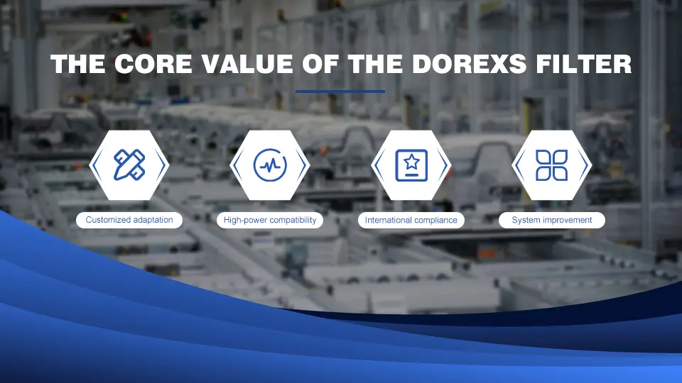
- Customized Solutions: Tailored for different switching frequencies, high dv/dt conditions, and compact cabinet layouts
- High-Current Compatibility: High-saturation cores maintain performance from 1–100 A
- Global Certification: cUL, CE, CQC, RoHS compliant
- Enhanced Reliability: Reduces MCU resets, false triggering, and noise-induced failures
2. Extended Application Scenarios
Beyond general-purpose motor drives (1–7.5 kW), the solution applies to:
- EV drive systems
- Industrial robot servo controllers
- High-power inverters
- Charging pile modules
- EMI-sensitive industrial electronics
Conclusion
EMI mitigation for motor drive controllers is a systematic engineering task involving noise mechanism analysis, targeted component selection, professional filter use, proper installation, grounding, and PCB co-design.
DOREXS EMI filters deliver precise CM/DM suppression and, combined with standardized installation, enable rapid EMC certification while improving reliability and noise immunity. This solution provides a robust, repeatable methodology for EMI control in industrial electronic systems.
DOREXS EMI filters deliver precise CM/DM suppression and, combined with standardized installation, enable rapid EMC certification while improving reliability and noise immunity. This solution provides a robust, repeatable methodology for EMI control in industrial electronic systems.
FAQ
1. Why are motor drive controllers prone to EMI over-limit issues?
High-frequency PWM switching produces extreme dv/dt and di/dt values, and long motor cables create strong CM resonance, concentrating noise between 150 kHz and 30 MHz.
2. Can EMI filters solve all EMI over-limit problems?
No. Filters are essential, but EMI mitigation requires PCB routing optimization, proper grounding, correct cable layout, and CM suppression at the motor output.
3. Is CM suppression at the motor output necessary?
Yes. For cable lengths >3 m, CM radiation increases sharply due to the antenna effect. CM chokes or shielded cables are essential.
4. How do DOREXS EMI filters outperform ordinary filters?
- Stronger CM attenuation (22–35 dB)
- Smoother DM attenuation (14–26 dB)
- High-current non-saturation
- Engineered structure preventing high-frequency roll-off
- Customization for specific drive models
They are designed as engineering-grade filters for industrial drive applications.
EMI Interference in CNC Equipment & DOREXS Industrial Filter Solutions
EMI Issues in Industrial Robots and How DOREXS EMI Filters Deliver Reliable Solutions
Related Article
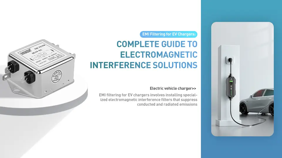
This guide covers DC and AC EMI filtering solutions, regulatory compliance requirements, and practical implementation strategies for charging station operators, OEMs, and facility managers.
EMI Filtering for EV Chargers: Complete Guide to Electromagnetic Interference Solutions
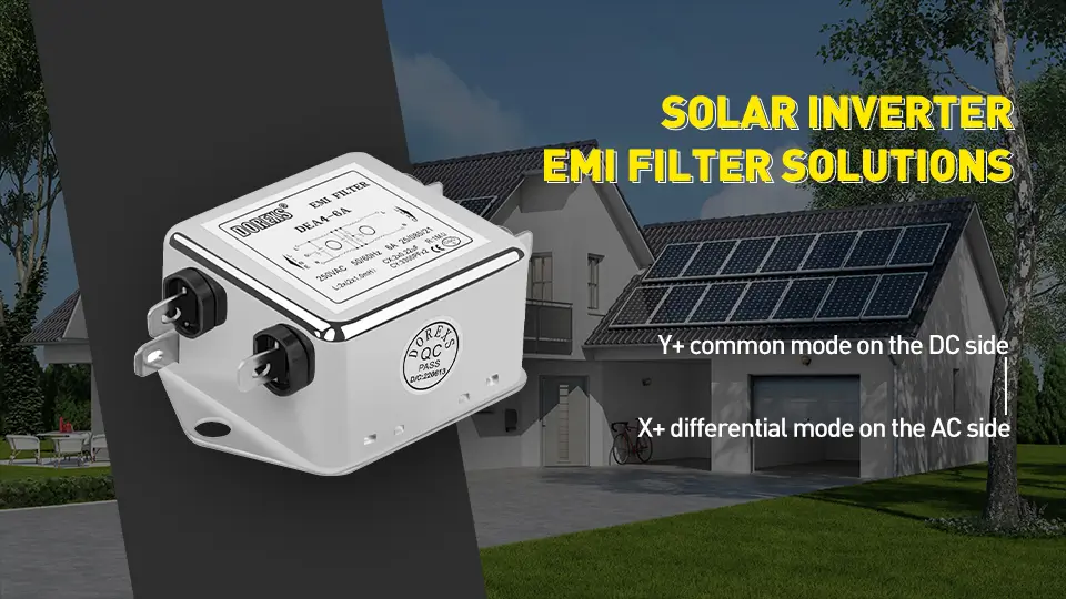
EMI from solar power systems can affect the performance of sensitive electronic devices, such as computers, medical devices, appliances, electrical devices, and other devices.
Solar Inverter EMI Filter Solutions: Professional EMC Solutions for Grid-Tied and PV Inverter Systems

In today’s fast-growing smart manufacturing era, CNC machines are expected to deliver not only machining capability but consistent precision, long-term stability, and zero-downtime reliability.However, as machine power increases and electronic components operate at higher speeds, EMI (Electromagnetic Interference) has become one of the most serious hidden threats in CNC systems.
EMI Interference in CNC Equipment & DOREXS Industrial Filter Solutions
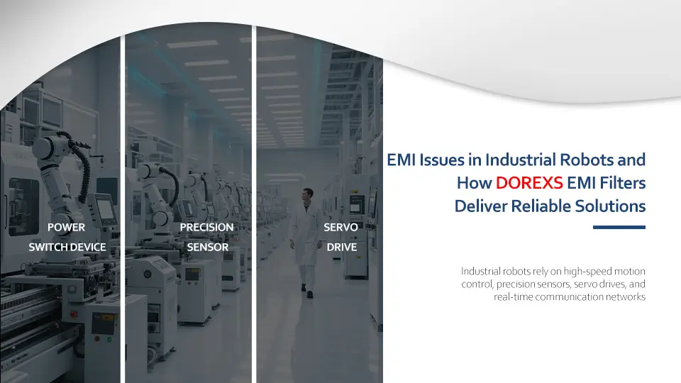
Industrial robots rely on high-speed motion control, precision sensors, servo drives, and real-time communication networks. These components make robotic systems extremely sensitive to electromagnetic interference (EMI). Ensuring electromagnetic compatibility is critical for reliable robot operation.
EMI Issues in Industrial Robots and How DOREXS EMI Filters Deliver Reliable Solutions