How DOREXS Solved Conducted EMI in a Negative Ion Fan Using a Two-Stage EMI Filter
Application: Negative Ion Fan
Power Supply: 120VAC / 60Hz
EMI Filter: DOREXS DEA4-6A
EMC Challenge: Excessive Conducted Emissions
Solution: Two-Stage EMI Filter + Clamp-On Ferrite Core
Result: Conducted Emission Test Passed
1. Project Background
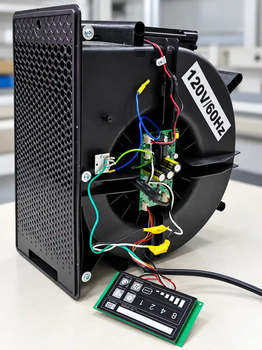
Negative ion fans combine airflow generation with electronic control systems to support air treatment and purification applications.
These devices typically integrate fan motors, control circuits, and power conversion components within a compact structure.
However, high-frequency electrical noise generated by electronic control circuits can couple onto AC power lines, creating conducted electromagnetic interference (EMI).
Without adequate suppression, this interference may cause equipment to fail electromagnetic compatibility (EMC) testing.
In this project, a 120VAC / 60Hz negative ion fan encountered significant conducted emission problems during EMC testing.
The initial measurements revealed excessive electromagnetic noise across the 150 kHz–10 MHz frequency range.
To resolve the issue, the engineering team investigated the interference source and implemented a two-stage EMI power filter supplied by DOREXS.
2. Initial EMC Test: Severe Conducted Emission Failure
The negative ion fan was evaluated over the conducted emission frequency range of 150 kHz–30 MHz.
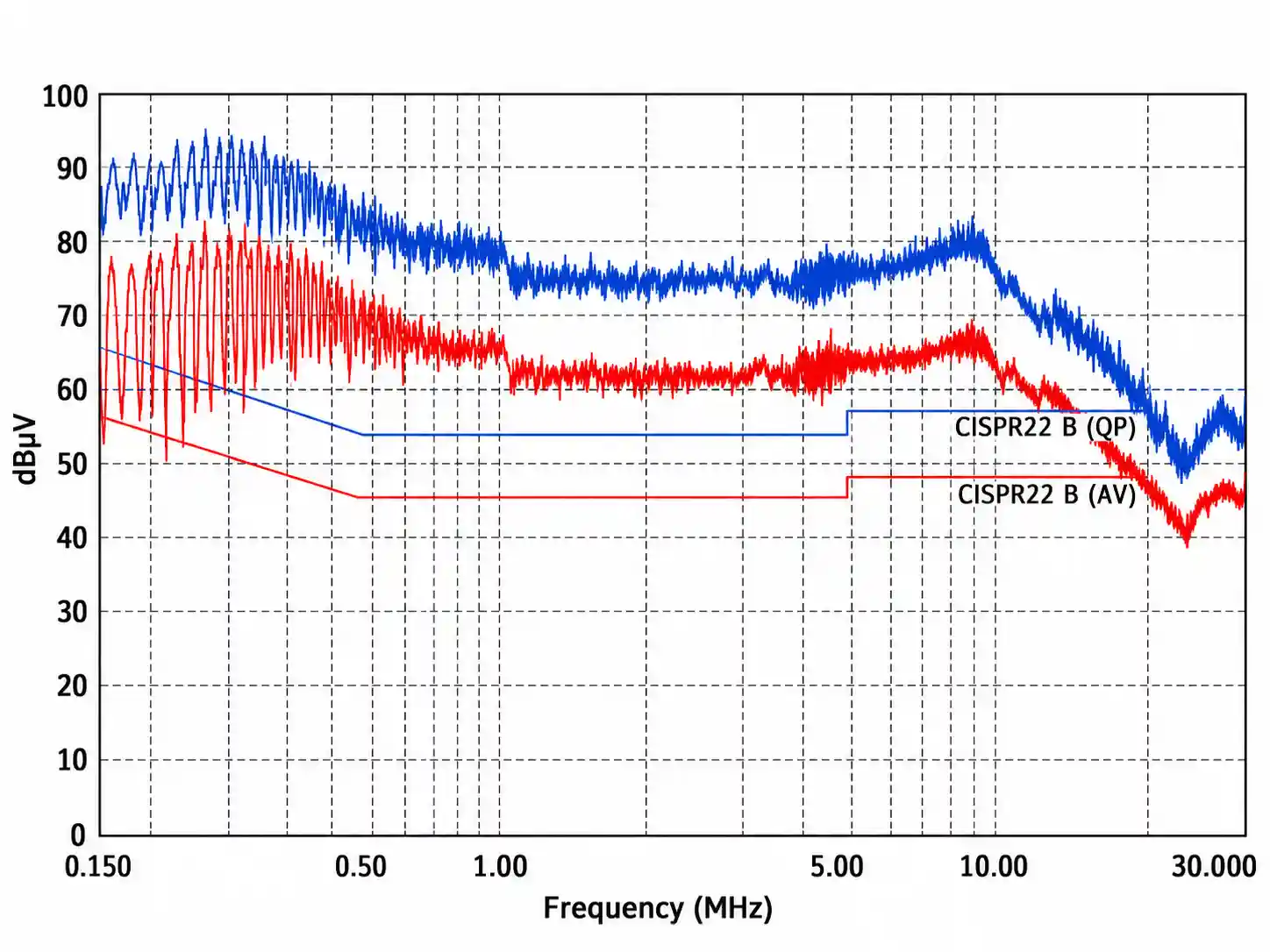
The measurement system displayed CISPR 22 Class B quasi-peak and average emission limits.
The initial results showed substantial electromagnetic interference across a broad frequency range, particularly between 150 kHz and 10 MHz.
According to the project investigation, emissions exceeded the applicable limits by more than 50 dB at certain frequencies.
This indicated that the equipment required significant conducted noise suppression.
Main EMC Problems
-
Excessive broadband conducted interference
-
High-frequency noise propagating through the AC power supply
-
Conducted emissions exceeding the displayed Class B limits
-
Need for an effective filtering solution compatible with the existing equipment
The first priority was to identify the dominant noise source before selecting an appropriate EMI filter.
3. EMI Troubleshooting: Identifying the Control Drive Board
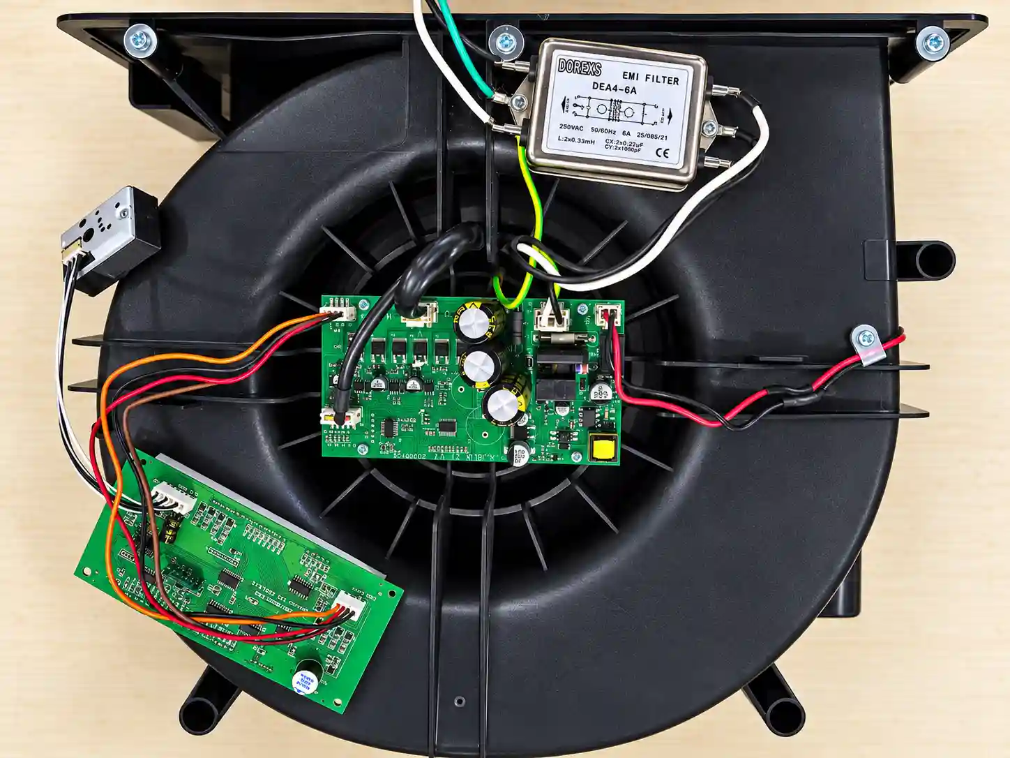
To locate the interference source, the engineers performed a diagnostic test with the fan motor switched off.
The measurements indicated that significant conducted interference remained even when the motor was not operating.
Further investigation identified the electronic control and drive board as a major contributor to the EMI problem.
This finding helped direct the troubleshooting process toward the electronic control circuitry rather than focusing exclusively on the motor.
Engineering Analysis
Electronic control boards may generate high-frequency electromagnetic noise through switching devices, power conversion circuits, and other rapidly changing electrical signals.
This noise can couple onto the AC power lines through conductive and parasitic coupling paths.
Depending on the circuit configuration, conducted interference may contain common-mode and differential-mode components.
These noise components require different suppression approaches, making the internal filter structure and system impedance important considerations.
For engineers investigating similar problems, understanding how EMI filters work can help identify suitable filtering strategies for power electronic equipment.
For this negative ion fan, the observed broadband interference suggested that a dedicated AC power line EMI filter would be an appropriate corrective measure.
4. First EMC Improvement: Installing the DOREXS DEA4-6A EMI Filter
Following the investigation, the engineers selected the DOREXS DEA4 series single-phase EMI filter.
The selected DEA4-6A model features a two-stage filtering structure designed to suppress conducted electromagnetic interference on AC power lines.
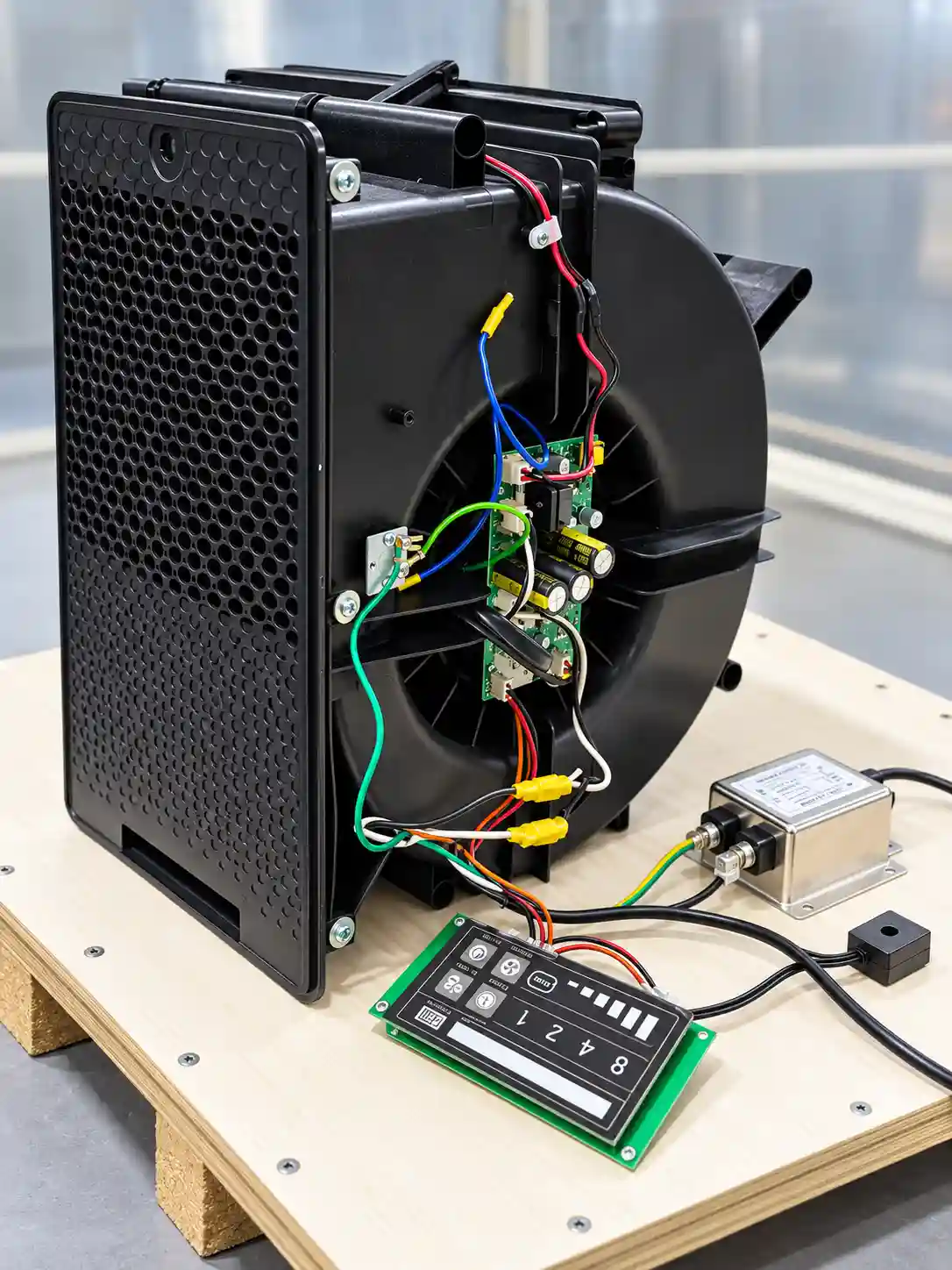
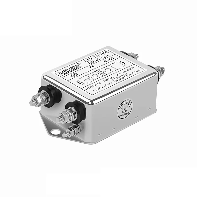
The filter was installed in the negative ion fan's AC power supply path to reduce high-frequency noise propagating toward the external power network.
EMI Filter Specifications
| Parameter | Specification |
|---|---|
| Manufacturer | DOREXS |
| Model | DEA4-6A |
| Filter Type | Two-Stage EMI Power Line Filter |
| Rated Current | 6A |
| Rated Voltage | 250VAC |
| Rated Frequency | 50/60Hz |
| Equipment Supply | 120VAC / 60Hz |
| Application | Negative Ion Fan |
Why Was a Two-Stage EMI Filter Selected?
A two-stage EMI filter uses multiple inductive and capacitive filtering sections to attenuate conducted electromagnetic noise.
Compared with a simpler single-stage topology, a properly designed two-stage filter may provide increased attenuation over a wider frequency range.
This makes two-stage filtering particularly useful for equipment exhibiting substantial broadband conducted interference.
The DEA4-6A was selected because the negative ion fan exhibited significant noise over a broad frequency range.
For similar electronic appliances and AC-powered equipment, DOREXS also offers a wider range of single-phase EMI filters with different current ratings, mounting options, and filtering configurations.
First Test Result
After installing the two-stage EMI filter, the engineers performed another conducted emission test.
The measurements showed a significant reduction in broadband interference.
However, a remaining emission peak near 16 MHz still exceeded the applicable limit by approximately 2 dB.
Although the EMI filter addressed most of the interference problem, further optimization was necessary to achieve the required EMC performance.
5. Second EMC Improvement: Ferrite Core Optimization
To suppress the remaining high-frequency emission peak, the engineering team introduced an additional filtering measure.
A nickel-based clamp-on ferrite core was installed at the input side of the DOREXS EMI filter, with the power cable routed through the core for one turn.

Why Add a Ferrite Core?
Ferrite materials provide frequency-dependent impedance that can help attenuate high-frequency interference currents.
Their effectiveness depends on several factors, including:
-
Ferrite material characteristics
-
Operating frequency
-
Core dimensions
-
Number of cable turns
-
Cable routing and current configuration
-
Source and load impedance
In this application, the ferrite core was used as a supplementary suppression component to address the remaining emission near 16 MHz.
The combination of the two-stage EMI filter and ferrite core provided a more effective system-level EMI suppression solution.
The project also demonstrates why engineers must consider filtering performance together with cable routing, parasitic coupling, and installation conditions.
For additional technical information about filter components, noise propagation, and EMC design, see the DOREXS EMI Filter Basics guide.
6. Final EMC Test: Conducted Emissions Successfully Reduced
After installing both the DOREXS DEA4-6A EMI filter and the additional ferrite core, the engineers conducted the final EMC measurement.
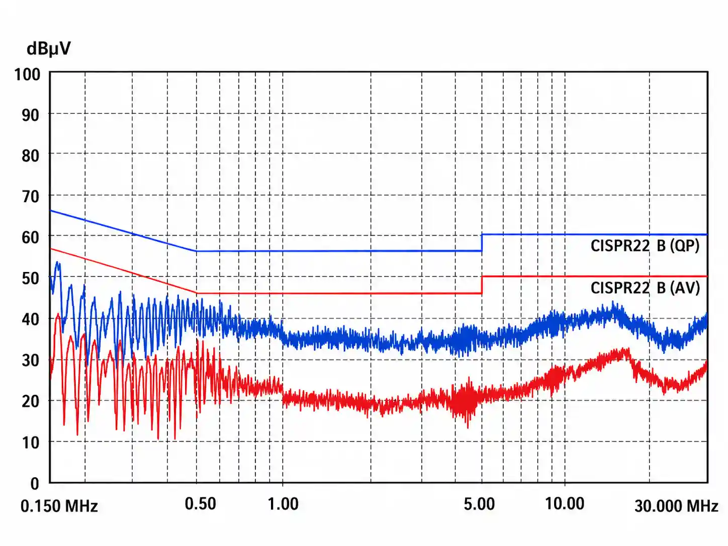
The final test curve showed a substantial reduction in conducted emissions compared with the initial measurement.
Both the quasi-peak and average emission traces remained below the displayed Class B limit lines across the measured frequency range.
According to the project test results, the negative ion fan successfully met the intended conducted emission requirements.
Before and After EMI Suppression
| Parameter | Initial Test | Final Test |
|---|---|---|
| Frequency Range | 150 kHz–30 MHz | 150 kHz–30 MHz |
| Conducted EMI | Severe broadband interference | Significantly reduced |
| Main Problem | Excessive emissions from control electronics | Noise suppressed |
| EMI Filtering | Original equipment configuration | DEA4-6A + ferrite core |
| Test Result | Failed | Passed |
The final measurements confirmed that the combined filtering approach effectively reduced the conducted electromagnetic interference affecting the negative ion fan.
7. Engineering Insights from the Project
Identify the Actual Interference Source
The troubleshooting process showed that the control and drive board was a major source of interference, even when the fan motor was switched off.
This highlights the importance of evaluating electronic control circuits during EMC diagnosis.
Select the Appropriate EMI Filter Structure
The initial emissions extended across a broad frequency range, making a two-stage filtering solution a suitable option for the application.
Pay Attention to Residual High-Frequency Emissions
Although the EMI filter substantially reduced conducted emissions, a remaining 16 MHz peak required additional suppression.
This illustrates why a successful filter installation must be verified through actual EMC measurements.
Combine Filtering with System-Level Optimization
The final result was achieved through the combined use of a two-stage EMI filter and a clamp-on ferrite core.
In practical EMC engineering, filter selection, cable routing, grounding, and supplementary suppression components should be evaluated together.
8. DOREXS EMI Filter Solutions for Negative Ion Fans
DOREXS develops and manufactures EMI/EMC filters for electronic appliances, ventilation equipment, industrial fans, electronic control systems, motor drives, and other applications requiring conducted noise suppression.
The DEA4 series offers a two-stage filtering configuration suitable for applications requiring enhanced conducted EMI attenuation.
DOREXS also supports customized EMI filter selection and EMC troubleshooting based on equipment voltage, current, interference characteristics, and installation requirements.
Whether your equipment experiences broadband conducted interference, residual high-frequency emission peaks, or difficulties meeting EMC requirements, selecting the appropriate EMI filter and optimizing its installation can improve overall EMC performance.
Need help solving conducted EMI problems in your equipment?
Contact DOREXS for EMI filter selection and EMC engineering support.
Frequently Asked Questions
What causes conducted EMI in a negative ion fan?
Conducted EMI may originate from electronic control boards, switching power supplies, motor drive circuits, or other high-frequency switching components. In this project, the control and drive board was identified as a major interference source.
Why was a two-stage EMI filter used?
A two-stage EMI filter can provide additional attenuation of conducted interference over a broad frequency range. The DOREXS DEA4-6A was selected to address the severe broadband emissions observed during testing.
Why was a ferrite core required after installing the EMI filter?
The two-stage filter significantly reduced the interference, but a residual emission near 16 MHz remained approximately 2 dB above the limit. The additional ferrite core helped suppress this remaining high-frequency noise.
Can an EMI filter guarantee EMC compliance?
No. EMC performance depends on the complete equipment design, filtering components, installation, grounding, and operating conditions. Compliance must be confirmed through appropriate testing.
EMI Filtering for EV Chargers: Complete Guide to Electromagnetic Interference Solutions
Related Article