EMI Filtering for EV Chargers: Complete Guide to Electromagnetic Interference Solutions
Introduction
EMI filtering for EV chargers prevents electromagnetic interference from disrupting charging operations, damaging electric vehicles, and affecting nearby electronic systems. As EV charging stations proliferate across residential, commercial, and industrial settings, the high-frequency switching inherent in power conversion creates electromagnetic noise that threatens both charger performance and regulatory compliance.
This guide covers DC and AC EMI filtering solutions, regulatory compliance requirements, and practical implementation strategies for charging station operators, OEMs, and facility managers. The content addresses conducted and radiated EMI challenges specific to modern charging infrastructure, from Level 2 AC chargers to ultra-fast DC systems exceeding 350kW. Whether you’re specifying filters for new installations or troubleshooting interference issues in existing ev charging stations, this resource provides actionable technical guidance.

EMI filtering for EV chargers involves installing specialized electromagnetic interference filters that suppress conducted and radiated emissions, ensuring charging stations meet safety standards like CISPR25 and FCC Part 15 while preventing interference with nearby electronic devices and communication systems.
By the end of this guide, you will understand:
-
Primary EMI sources in charging systems and their impact on performance
-
How to select appropriate emi filters for specific charger configurations
-
Regulatory compliance pathways for different markets
-
Cost-effective filtering solutions that balance performance with budget constraints
-
Installation practices that optimize filter effectiveness and charger reliability
Understanding Electromagnetic Interference in EV Charging Systems
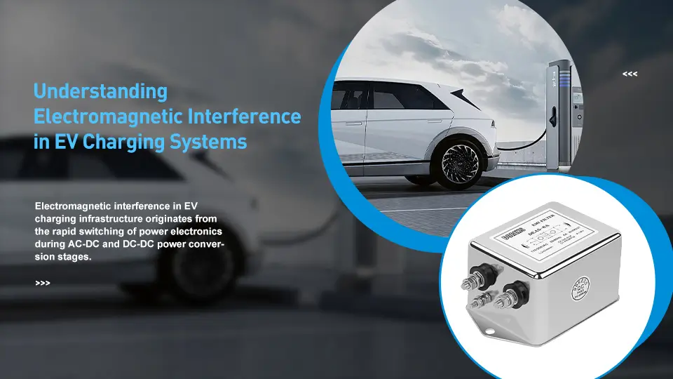
Electromagnetic interference in EV charging infrastructure originates from the rapid switching of power electronics during AC-DC and DC-DC power conversion stages. Every time a transistor switches on or off—potentially millions of times per second in modern chargers—it generates electromagnetic noise across a broad frequency spectrum. This noise can propagate through power lines to the grid, radiate through the air to affect nearby devices, or travel through cables to compromise battery management systems and onboard chargers.
Primary EMI sources in charging stations include AC-DC converters that rectify grid power, DC DC converters that regulate voltage for battery charging, switching power supplies for auxiliary systems, and high-voltage cables carrying pulsating current. Each component contributes to the overall electromagnetic signature of the installation.
Conducted vs Radiated EMI in Charging Stations
Conducted EMI travels along power lines and charging cables, using electrical conductors as transmission paths. This interference type typically spans from 150 kHz to 30 MHz and directly affects grid power quality, potentially causing voltage spikes that impact other devices connected to the same electrical distribution system. Conducted emissions also travel through signal lines and communication cables, corrupting data transmission between the charger and vehicle or between the charger and network management systems.
Radiated EMI propagates through space as electromagnetic waves, escaping from cables, enclosures, and components to affect sensitive equipment in close proximity. This radiation can disrupt Wi-Fi networks, cellular communications, Bluetooth connections, and even medical devices like pacemakers. The intensity of radiated emi depends on cable routing, enclosure shielding effectiveness, and the frequency content of switching waveforms.
High-Frequency Switching Challenges
Modern ev chargers increasingly use wide bandgap semiconductors—silicon carbide (SiC) and gallium nitride (GaN)—to achieve higher efficiency and compact design. SiC devices operate at switching frequencies up to 1 MHz, while GaN transistors can reach 4 MHz or higher. These elevated frequencies improve power density and reduce passive component size, but they generate harmonics that extend into critical communication bands.
The 2.4 GHz and 5 GHz frequency bands used by Wi-Fi, Bluetooth, and other wireless systems become vulnerable to interference from high-order harmonics. Charging stations with inadequate filtering can effectively jam wireless communications within their vicinity, creating operational problems for payment systems, remote monitoring, and vehicle-to-grid communication protocols.
Understanding these EMI generation mechanisms establishes the foundation for selecting appropriate mitigation techniques.
EMI Filtering Technologies for EV Chargers
EMI filtering technologies fall into distinct categories based on their operating principles, voltage ratings, and application requirements. Effective emi mitigation typically combines multiple filter types positioned at strategic points throughout the charging system to address both conducted and radiated emissions.

AC Line EMI Filters
Three-phase emi filters at the grid connection point represent the first line of defense against conducted emissions. Delta and delta-wye filter configurations accommodate different utility connection schemes while providing attenuation across the regulated frequency spectrum.
Current ratings scale with charger power levels: 16A filters suit 7kW residential chargers, while 630A units handle 350kW ultra-fast DC systems. Insertion loss specifications indicate how effectively the filter attenuates noise at specific frequencies—typically measured in decibels (dB) from 150 kHz through 30 MHz. Higher insertion loss values indicate better noise suppression but may increase filter size and cost.
AC line filters typically incorporate both common mode and differential mode filtering elements within a single package, simplifying installation while addressing both interference pathways. Filter selection must account for line voltage (typically 400-480VAC for commercial installations), current capacity with adequate margin for inrush conditions, and ambient temperature range for outdoor installations.
High Voltage DC EMI Filters
DC EMI filters address interference on the high-voltage output connecting charger to vehicle. These filters must withstand voltages up to 1500VDC while handling currents from 450A for standard DC fast chargers to 1600A for the highest-power industrial chargers.
Y-capacitor selection in DC filters requires careful attention to safety considerations. Unlike AC applications where leakage current limits are well-established, DC isolation requirements demand specialized capacitor types rated for the full system voltage with appropriate safety margins. Improper capacitor selection can create shock hazards or fail to meet safety regulations.
DC emi filters reduce the high-frequency noise that would otherwise radiate from charging cables, which act as antennas at megahertz frequencies. Installing an appropriate DC filter at the charger output significantly reduces radiated emissions without requiring extensive cable shielding.
Common Mode and Differential Mode Filtering
Common mode chokes suppress noise appearing simultaneously on both power conductors relative to ground. These components use magnetic cores wound with paired conductors, creating inductance that opposes common mode currents while allowing differential (normal) current to flow unimpeded. Common mode filtering addresses the primary mechanism by which noise couples to ground planes and radiates from cables.
Differential mode filtering targets line-to-line noise using LC networks—combinations of inductors and capacitors tuned to attenuate specific frequencies or frequency ranges. Active and passive filters may be combined in sophisticated designs: passive filters handle high-frequency content above 2-3 MHz, while active filters cancel lower-frequency interference through phase-inverted signal injection.
Ferrite bead and core selection must account for the extreme temperature range of automotive applications: -40°C to +125°C. Magnetic properties vary significantly with temperature, and cores selected without thermal analysis may provide inadequate filtering at temperature extremes.
Regulatory Standards and Compliance Requirements
Regulatory compliance determines whether charging equipment can legally operate in a given market. EMI standards exist to protect radio communications, ensure electromagnetic compatibility with other devices, and maintain grid power quality. Non-compliant chargers face rejection at the grid connection approval stage, potentially stranding significant capital investments.
International EMI Standards for EV Chargers
CISPR25 specifies automotive EMI requirements with test methods covering both conducted and radiated emissions from vehicle-mounted equipment. While primarily targeting onboard chargers and vehicle electronics, CISPR25 methods increasingly apply to the vehicle-side interface of external charging equipment.
FCC Part 15 governs unintentional radiators in the United States, establishing conducted and radiated emission limits for commercial charging equipment. Class A limits apply to industrial and commercial installations, while stricter Class B limits apply to equipment marketed for residential use.
IEC 61851 addresses charging station safety standards comprehensively, including provisions for electromagnetic interference that could affect vehicle battery management systems or create hazards. This standard covers communication protocols, connector requirements, and electrical safety in addition to EMI provisions.
EN 55011 sets industrial equipment EMI requirements applicable to DC fast chargers and other high-power charging systems in European markets. This standard categorizes equipment by intended installation environment and specifies corresponding emission limits, ensuring adherence to European market access requirements.
Testing and Certification Process
EMI compliance testing follows a structured progression:
-
Pre-compliance testing identifies emission sources and evaluates filter effectiveness using simplified test setups, allowing iterative design refinement before formal testing
-
Full compliance testing at accredited laboratories measures conducted emissions using LISN (Line Impedance Stabilization Network) equipment and radiated emissions in anechoic chambers
-
Documentation preparation compiles test reports, technical construction files, and declarations of conformity for regulatory submission
-
Certification body review verifies documentation completeness and test validity before issuing compliance certificates
Timeline from design completion to certification typically spans 8-16 weeks, depending on laboratory availability and any required design iterations. Testing costs range from $15,000 for basic AC chargers to $50,000+ for complex DC fast charging systems requiring multiple test configurations.
Regional Compliance Variations
North American markets governed by FCC regulations use different frequency bands and test methodologies than European CISPR-based requirements. Asian markets often reference IEC standards but may impose additional national requirements. Japan, Korea, and China each maintain distinct certification processes.
Frequency band differences affect filter design: European requirements extend to 1 GHz for radiated emissions, while FCC Part 15 measurements typically stop at 960 MHz. These variations mean filters optimized for one market may require modification for global deployment.
Certification markings—CE for Europe, FCC logo for the US, CCC for China—must appear on compliant equipment. Multi-market products require compliance with all applicable standards, potentially increasing component count and cost.
EMI Filter Selection and Implementation
Practical filter selection begins with understanding the specific EMI challenges of the charging system under consideration. Systematic evaluation of power levels, switching frequencies, and installation constraints guides optimal component selection.

Filter Sizing and Specification Process
Calculate EMI filter requirements using measured or estimated noise spectra from the power converters. Pre-compliance EMI measurements identify the frequencies requiring maximum attenuation, guiding insertion loss specifications. A charger producing 80 dB of noise at 500 kHz while facing a 60 dB limit needs filters providing at least 20 dB of insertion loss at that frequency—plus margin for measurement uncertainty and manufacturing variation.
Form factor selection depends on installation constraints. Chassis-mount filters integrate within charger enclosures, panel-mount units attach to cabinet walls, and inline filters install within cable assemblies. High power levels demand attention to thermal management; filters dissipate power as heat, and inadequate cooling reduces filter life and effectiveness.
Current rating selection requires margin above maximum operating current to accommodate transient conditions. A 200A charger typically uses filters rated for 250A or higher to ensure reliable operation across all operating conditions without thermal stress.
Installation Best Practices
Grounding technique critically determines filter effectiveness. Low-impedance ground connections—short, wide conductors attached to clean, unpainted metal surfaces—minimize ground path inductance that would otherwise allow noise to bypass the filter. A good fit between filter grounding provisions and installation grounding infrastructure prevents compliance failures.
Cable routing must separate input and output circuits to prevent filtered noise from coupling back into the system. Running input and output cables in parallel or within the same conduit defeats the purpose of filtering. Maintain maximum practical separation, ideally routing cables on opposite sides of the enclosure.
Enclosure shielding requirements escalate with charger power. Continuous conductive gaskets seal panel seams, ventilation openings use honeycomb filters, and cable entry points use shielded connectors or glands. These measures contain radiated emissions within the enclosure.
DOREXS Power Filter Advantages
DOREXS power filters address the specific challenges of EV charging applications through purpose-built design. Compact form factor benefits space-constrained charging station designs where cabinet volume commands premium pricing. The reduced footprint allows integration without major cabinet redesigns, preserving existing mechanical packaging.
Superior insertion loss performance across automotive frequency bands (150 kHz to 108 MHz) exceeds requirements for global market compliance. This margin ensures reliable certification across regional variations and provides headroom for field installation variables that might otherwise compromise marginal designs.
High-current handling capabilities reach 1000A, supporting ultra-fast charging applications at high power levels without paralleling multiple filter units. Single-filter solutions simplify installation, reduce connection points that could develop resistance over time, and minimize maintenance requirements.
Enhanced thermal design suits outdoor charging station environments where temperature extremes stress components and cooling options are limited. Robust thermal performance ensures consistent filtering across seasonal temperature variations without derating or supplemental cooling systems.
Modular design philosophy allows easy integration into diverse charger architectures, supporting both new product development and field upgrades of existing installations experiencing EMI compliance issues.
Common EMI Challenges and Solutions
Field installations encounter predictable EMI problems that proven mitigation strategies can address. Understanding common failure modes accelerates troubleshooting and prevents recurring issues.
Grid Connection EMI Issues
Install three-phase EMI filters at the utility connection point, ensuring proper grounding to the building electrical system’s main grounding electrode. This placement intercepts conducted emissions before they reach the utility distribution system while protecting the charger from incoming grid noise.
Implement power factor correction to reduce harmonic distortion and associated EMI generation. Poor power factor causes current waveform distortion that increases EMI across low-frequency bands and may trigger utility power quality complaints.
Wireless System Interference
Target filtering at 2.4 GHz and 5 GHz bands prevents disruption to Wi-Fi, cellular, and Bluetooth communications essential for charger operation. Additional shielding around high-frequency switching components and cables contains emissions at their source.
Ferrite cores on communication cables provide supplemental high-frequency noise suppression without requiring cable replacement. Position cores near cable entry points to the charger enclosure for maximum effectiveness.
Medical Device Compatibility
Enhanced EMI filtering protects pacemaker and medical implant users within the 30 cm threshold specified in safety standards. Warning signage alerts users with implanted devices to maintain safe distances during charging operations.
Installations near medical facilities or in areas with elderly populations may require additional filtering beyond minimum compliance levels to mitigate interference risks comprehensively.
Cable and Connector EMI
Select shielded charging cables with proper connector grounding for high-power applications. Cable shields must terminate at both ends with low-impedance connections to charger and vehicle chassis for effective shielding performance.
Install ferrite cores on signal and communication cables to suppress high-frequency noise coupling through non-power conductors. V2G communication systems and pilot signal lines prove particularly susceptible to interference without supplemental filtering.
Conclusion and Next Steps
Proper EMI filtering ensures EV charging stations operate safely, achieve regulatory approval, and coexist with surrounding electronic systems. As charging power levels increase and wide bandgap semiconductors push switching frequencies higher, filtering requirements become more demanding—making component selection and installation quality increasingly important.
Immediate action items:
-
Conduct EMI pre-compliance testing on current or prototype charger designs to identify filtering requirements
-
Evaluate filter solutions against power rating, frequency requirements, and form factor constraints
-
Plan installation timeline accounting for lead times on specialized filtering components
-
Engage accredited test laboratories for compliance verification before market deployment
Related topics worth exploring include harmonic distortion mitigation for grid power quality, power quality optimization for reduced energy costs, and emerging active filtering technologies that may offer performance advantages in future charging system designs.
Additional Resources
-
EMI filter sizing calculators correlating charger specifications with filter requirements
-
Regulatory compliance checklists organized by region (FCC, CISPR, CCC)
-
DOREXS technical specifications and application notes for EV charging applications
-
Industry white papers addressing advanced EMI mitigation techniques for high-power charging systems
Solar Inverter EMI Filter Solutions: Professional EMC Solutions for Grid-Tied and PV Inverter Systems
Related Article