What Is an RFI Filter? How It Works, Applications, and Selection Guide
Radio frequency interference can travel through power cables, signal lines, grounding paths, and parasitic coupling paths inside electrical equipment. In industrial systems, switching power supplies, variable frequency drives, servo drives, inverters, relays, and high-speed switching devices can all generate unwanted high-frequency noise.
An RFI filter, or radio frequency interference filter, is used to reduce this unwanted high-frequency interference while allowing the required power or signal to pass.
For equipment manufacturers, however, choosing an RFI filter involves more than simply matching voltage and current ratings. The noise frequency, common-mode and differential-mode behavior, grounding, leakage current, installation position, cable routing, and applicable EMC requirements can all affect real-world filter performance.
This guide explains what an RFI filter is, how it works, how RFI differs from EMI, where RFI filters are used, and how engineers can select the right filter for an electrical or electronic system.

What Is an RFI Filter?
An RFI filter is an electrical filter designed to attenuate unwanted radio-frequency interference traveling along power or signal conductors.
In power applications, an RFI filter is commonly installed between the power source and the equipment. It allows the required DC or 50/60 Hz AC power to pass while presenting a much higher impedance or alternative return path to unwanted high-frequency noise.
Most industrial power-line RFI filters are passive networks containing components such as:
-
Common-mode chokes
-
Differential-mode inductors
-
X capacitors
-
Y capacitors
-
Discharge or damping resistors
These components work together to attenuate high-frequency interference without significantly affecting normal power delivery.
In practice, the terms "RFI filter," "EMI filter," "EMC filter," "mains filter," and "power line filter" are sometimes used interchangeably, particularly when referring to filters installed at the power input of electrical equipment.
What Does RFI Mean?
RFI stands for Radio Frequency Interference.
It describes unwanted electromagnetic energy within radio-frequency ranges that interferes with the normal operation of electrical or electronic equipment.
Potential RFI sources include:
-
Switching power supplies
-
Variable frequency drives
-
Servo amplifiers
-
DC/DC converters
-
Inverters
-
High-speed digital electronics
-
Electric motors and switching devices
-
Relays and contactors
-
Communication equipment
-
Long motor and power cables
In modern industrial equipment, power semiconductors switch rapidly between voltage states. These fast voltage and current transitions contain high-frequency spectral components that may couple into power cables, chassis structures, protective earth conductors, control wiring, and nearby circuits.
As a result, a switching device operating at only a few kilohertz can still produce interference extending much higher into the frequency spectrum.
Is RFI the Same as EMI?
Not exactly.
EMI, or electromagnetic interference, is the broader term. RFI refers specifically to interference involving radio-frequency energy.
For practical EMC engineering, however, the terminology frequently overlaps. A manufacturer may describe the same power-line component as an:
-
EMI filter
-
RFI filter
-
EMI/RFI filter
-
EMC filter
-
Line filter
The name is less important than the filter’s actual electrical characteristics. A more detailed comparison is available in this guide to the difference between EMI and RFI filters.
When selecting a filter, engineers should focus on:
-
Frequency-dependent insertion loss
-
Common-mode attenuation
-
Differential-mode attenuation
-
Rated voltage
-
Rated current
-
Leakage current
-
Filter topology
-
Source and load impedance
-
Grounding
-
Installation environment
The product should not be selected only because it is labeled “RFI filter” or “EMI filter.”
How Does an RFI Filter Work?

Most power-line RFI filters behave primarily as low-pass filters.
The basic objective is simple:
Allow low-frequency power to pass while attenuating unwanted high-frequency noise.
At normal power frequencies such as 50 Hz or 60 Hz, the inductors and capacitors are selected so that the filter has minimal effect on normal equipment operation.
As frequency increases, their behavior changes.
Inductors present increasing impedance to high-frequency current, while capacitors provide controlled paths for high-frequency interference.
The result is an LC filtering network that reduces the amount of RF noise propagating between the equipment and the external power network.
Typical power flow can be represented as:
AC Power Source → RFI/EMI Filter → Equipment
For noise generated inside the equipment, the filter helps prevent conducted interference from traveling back onto the mains.
For interference arriving from the external power network, the same filter can also help reduce the noise reaching sensitive internal electronics.
This means power-line RFI filters can provide bidirectional conducted noise attenuation.
Main Components Inside an RFI Filter
Understanding the components helps explain why different RFI filters perform differently.
Common-Mode Choke
A common-mode choke presents high impedance to common-mode interference while allowing the normal load current to pass.
The desired current flowing through line and neutral generates opposing magnetic flux that largely cancels inside the magnetic core.
Common-mode noise, however, flows in the same direction relative to ground. The magnetic flux therefore reinforces instead of cancelling, producing a much higher impedance to the unwanted noise.
X Capacitor
An X capacitor is normally connected between conductors such as line and neutral.
Its primary role in a typical mains filter is to help attenuate differential-mode noise.
At high frequencies, the capacitor provides a lower-impedance path that helps return differential noise toward its source.
Y Capacitor
Y capacitors are normally connected from line conductors toward protective earth or chassis.
They are particularly important for controlling common-mode noise.
The common-mode choke and Y capacitors form a low-pass network for common-mode interference, while X capacitance and inductance contribute to differential-mode suppression.
The value of Y capacitance must be selected carefully because it also influences leakage current.
This becomes especially important in applications such as medical equipment, measurement equipment, or other systems with strict leakage-current requirements.
Differential-Mode Inductor
Some filters include dedicated differential-mode inductance to improve attenuation between power conductors.
Multi-stage or high-performance filters may combine common-mode and differential-mode elements to achieve stronger attenuation across a wider frequency range.
Common-Mode vs Differential-Mode RFI
One of the most important steps in solving an EMC problem is determining whether the dominant interference is common mode or differential mode.

Differential-Mode Noise
Differential-mode noise flows between conductors.
In a single-phase AC system, for example, unwanted current may travel from:
Line → Load → Neutral
Typical suppression components include:
Differential inductance + X capacitors
Differential-mode interference is often associated with switching current loops, rectifiers, converters, and switching power supplies.
Common-Mode Noise
Common-mode noise appears on multiple conductors in the same direction relative to ground or chassis.
Its return path often involves:
-
Protective earth
-
Equipment chassis
-
Cable shields
-
Parasitic capacitance
-
Motor frames
-
Mechanical structures
Typical suppression components include:
Common-mode choke + Y capacitors
Common-mode interference is particularly important in VFDs, servo systems, inverters, and other systems with rapid voltage transitions and parasitic coupling to earth.
A filter optimized only for differential-mode noise may therefore perform poorly when the real problem is common-mode noise. See the complete explanation of differential-mode and common-mode noise for additional diagnostic guidance.
Does an RFI Filter Stop Radiated Interference?
This requires an important distinction.
A power-line RFI filter primarily controls conducted interference traveling on electrical conductors.
It does not act as a universal barrier that directly blocks every radiated electromagnetic field around the equipment.
However, conducted current on cables can contribute to radiated emissions because the cables themselves may behave like antennas.
Reducing RF current flowing on those cables can therefore also reduce some associated radiation.
When radiated emissions are the primary problem, additional EMC measures may be required, including:
-
Shielding
-
Cable shielding
-
360° shield termination
-
Grounding
-
Chassis bonding
-
Ferrite components
-
PCB layout optimization
-
Reduced switching loops
-
Improved cable routing
An RFI filter should therefore be considered one part of the overall EMC design rather than a solution to every interference problem.
RFI Filter vs EMI Filter
| RFI Filter | EMI Filter |
|---|---|
| Focuses on radio-frequency interference | Uses broader electromagnetic-interference terminology |
| Common term in power-line noise suppression | Common term in EMC engineering |
| Often targets high-frequency conducted noise | Can refer to the same filtering function |
| Frequently built from inductors and capacitors | Frequently built from inductors and capacitors |
| May be marketed as an RFI line filter | May be marketed as an EMI or EMC line filter |
In many industrial applications, there is no meaningful product-level distinction between a power-line RFI filter and an EMI filter.
The more useful engineering question is:
What type of noise must be attenuated, over what frequency range, and under what electrical and EMC conditions?
Types of RFI Filters
RFI filters are available in different configurations depending on the power system and equipment design.
Single-Phase RFI Filters
Single-phase EMI filters are used with equipment such as:
-
Power supplies
-
Control equipment
-
Test equipment
-
Industrial computers
-
Small automation systems
-
Medical equipment
They commonly filter line and neutral conductors.
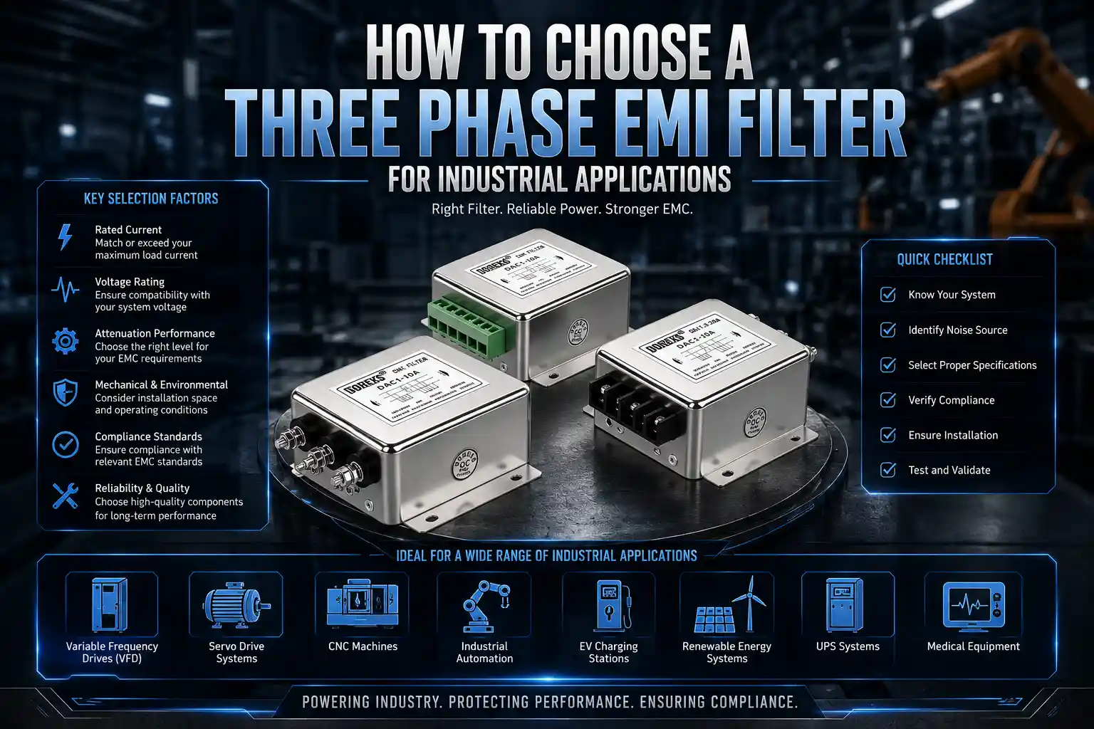
Three-Phase RFI Filters
Three-phase EMI filters are designed for industrial power systems and higher-power equipment.
Typical applications include:
-
Variable frequency drives
-
Servo systems
-
Industrial motor drives
-
CNC machinery
-
Robotics
-
Industrial power supplies
-
Renewable energy equipment
Filters may be designed for three-phase three-wire or three-phase four-wire systems depending on the application.
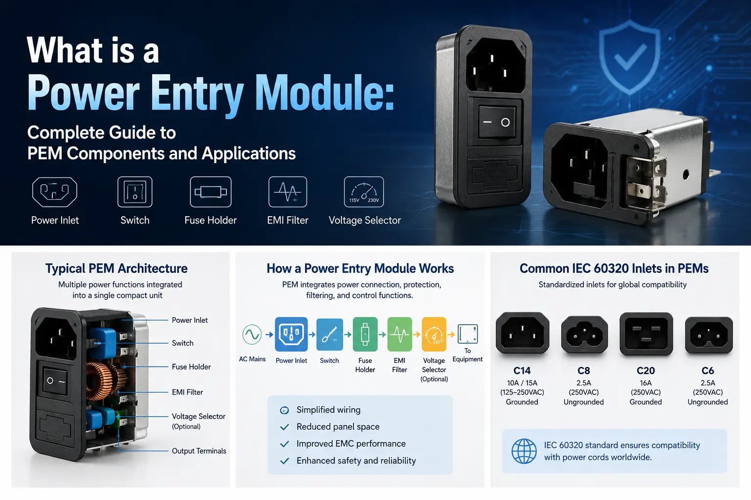
IEC Inlet RFI Filters
IEC inlet EMI filters integrate filtering directly into the equipment power-entry interface.
Some configurations may combine functions such as:
IEC inlet + EMI/RFI filter + fuse + switch
These configurations are often referred to as a power entry module. They are useful where equipment manufacturers need a compact AC power-entry design.
PCB RFI Filters
PCB-mounted filters are used where filtering must be integrated directly into electronic assemblies.
They are commonly used in control circuits, compact power supplies, instrumentation, and electronic equipment.
DC RFI Filters
DC power systems can also carry significant high-frequency switching noise.
DC EMI filters may be used in:
-
DC power supplies
-
EV charging equipment
-
Battery systems
-
Telecommunications
-
Industrial DC networks
-
Renewable energy systems
Feedthrough Filters
Feedthrough EMI filters provide filtering at the point where conductors enter or leave a shielded enclosure.
They are often used where high-frequency attenuation and effective enclosure integration are important.
Where Are RFI Filters Used?
Variable Frequency Drives
VFDs use high-speed semiconductor switching to generate variable-frequency motor output.
The rapid voltage transitions can produce common-mode and differential-mode noise that propagates through input power lines, motor cables, chassis structures, and grounding systems.
A suitable EMI filter for a VFD motor drive can help reduce conducted interference returning toward the AC supply.
However, VFD EMC performance can also depend on motor cable shielding, grounding, cable length, installation geometry, and drive configuration.
Servo Drive Systems
Servo amplifiers create similar switching-related interference.
Poor EMC design may contribute to problems such as:
-
Encoder errors
-
Communication instability
-
PLC interference
-
Sensor malfunction
-
Unexplained equipment resets
Filtering should therefore be coordinated with shielding, grounding, and cabinet layout.
Switching Power Supplies
Switch-mode power supplies generate high-frequency currents through their switching stages.
Power-entry RFI filters are frequently used to reduce noise returning onto the AC mains and to improve system-level EMC performance.
Industrial Automation
Industrial control cabinets may contain PLCs, power supplies, servo drives, VFDs, contactors, relays, communication modules, and sensors in a relatively small area.
RFI filtering can help prevent conducted interference from spreading between different parts of the system. Filter selection and cabinet design should be coordinated as part of the broader industrial automation EMI solution.
Medical and Measurement Equipment
Sensitive equipment may require both high attenuation and low leakage current.
In these applications, simply increasing Y capacitance to improve common-mode attenuation may not be acceptable.
The filter must therefore balance:
EMC performance + electrical safety + leakage-current requirements
A medical EMI filter should be evaluated in the context of the equipment’s complete leakage-current budget and applicable safety requirements.
How to Choose an RFI Filter
Selecting an RFI filter should start with the system rather than with the filter catalog.
1. Determine the Power System
Identify whether the equipment uses:
-
Single-phase AC
-
Three-phase three-wire
-
Three-phase four-wire
-
DC power
The filter topology must match the electrical system.
2. Confirm Operating Voltage
The selected filter must be appropriately rated for the system voltage.
For three-phase equipment, engineers should consider the relevant line-to-line and line-to-ground conditions.
3. Determine Maximum Operating Current
Filter current rating should be selected according to the actual maximum operating conditions, including expected load behavior and thermal conditions.
A filter should not be selected only from the equipment’s nominal operating current without considering the real application.
4. Identify the Problem Frequency
This is one of the most important selection criteria.
If EMC test results are available, determine:
-
Where the equipment exceeds the emission limit
-
Whether the problem is narrowband or broadband
-
Whether the dominant noise appears at lower or higher frequencies
-
Whether the noise is common mode or differential mode
The filter’s insertion-loss characteristics can then be compared with the actual interference spectrum.
5. Evaluate Insertion Loss
Insertion loss indicates how much a filter attenuates interference under specified test conditions.
Typical filter datasheets may provide separate curves for:
-
Common-mode insertion loss
-
Differential-mode insertion loss
These curves are much more useful than a generic claim such as “high attenuation.”
Real installed performance, however, can differ from standardized laboratory measurements because the source and load impedances in actual equipment may not match the test setup.
6. Check Leakage Current
Y capacitors improve common-mode attenuation but also contribute to current flowing toward earth.
Applications with strict leakage requirements may therefore require low-leakage filter designs.
7. Consider Mechanical Installation
Electrical performance alone is not enough.
Engineers should also consider:
-
Housing dimensions
-
Mounting style
-
Terminal configuration
-
Cooling
-
Ground connection
-
Cable entry direction
-
Available installation space
8. Match the Filter to the EMC Requirement
The relevant EMC requirement depends on the equipment type, application environment, target market, and product family.
For example, CISPR 11 addresses radio-frequency disturbance limits and measurement methods for industrial, scientific, and medical equipment. Other equipment categories may be governed by different product or product-family standards.
An RFI filter should therefore be selected as part of the system-level EMC compliance strategy, not because one filter is universally suitable for every standard.
For a broader evaluation process, consult the guide on how to select an EMI filter.
Where Should an RFI Filter Be Installed?
For power-line filtering, the filter should generally be installed as close as practical to the equipment power entry point.
This helps prevent unfiltered internal wiring from coupling noise around the filter.

A good arrangement is:
External Power Cable → RFI Filter → Short Internal Wiring → Equipment
Poor installation may allow noise to bypass even a high-performance filter.
Common installation mistakes include:
-
Long wires between the power entry and filter input
-
Long conductors between the filter output and the load
-
Routing filtered and unfiltered cables together
-
Crossing input and output wiring without adequate separation
-
Poor chassis bonding
-
Mounting the filter on painted or insulated surfaces without an effective bonding path
-
Using long or narrow grounding conductors with high high-frequency impedance
-
Placing noisy motor cables near clean power or signal wiring
-
Installing the filter far from the point where the cable enters the enclosure
-
Using an incorrect filter orientation when line and load sides are specified
Engineers should keep input and output conductors physically separated and minimize conductor length.
Where a metal filter housing is intended to bond to the chassis, the connection should be short and have low impedance at high frequencies. A long protective-earth wire may provide a safety connection but still perform poorly as an RF bonding path.
More practical details are covered in the EMI filter installation guide.
Why Filter Performance Can Differ in Real Equipment
Insertion-loss curves are normally measured under defined laboratory conditions. Real systems may have different source and load impedances, cable arrangements, grounding paths, and parasitic capacitances.
Performance may also be influenced by:
-
Filter position
-
Enclosure construction
-
Cable length
-
Source impedance
-
Load impedance
-
Motor and drive configuration
-
Switching frequency
-
Grounding and bonding quality
-
Temperature
-
Load current
-
Nearby noise coupling paths
A filter that performs well in one machine may therefore provide different attenuation in another system.
This is why EMC testing should be performed on the complete equipment configuration whenever possible.
Can a Larger RFI Filter Solve Every EMC Problem?
No.
Selecting a filter with a higher current rating does not automatically provide better attenuation. Current rating, filter topology, component values, leakage current, insertion-loss behavior, and the actual noise spectrum are separate considerations.
Likewise, adding more capacitance is not always an acceptable solution. Higher Y capacitance may increase leakage current, while resonance between the filter and the system can alter performance at certain frequencies.
If noise bypasses the filter through the chassis, cable shields, control wiring, or parasitic coupling, replacing the filter alone may not solve the problem.
The engineering process should therefore include:
-
Identify the dominant noise path.
-
Determine the relevant frequency range.
-
Separate common-mode and differential-mode contributions where possible.
-
Review filter selection and installation.
-
Evaluate shielding, grounding, bonding, and cable routing.
-
Test the complete equipment configuration.
DOREXS RFI and EMI Filter Solutions
DOREXS provides EMI/RFI filtering solutions for AC, DC, single-phase, three-phase, industrial, medical, and equipment power-entry applications.
Available filter categories include:
-
Single-phase EMI/RFI filters
-
Three-phase EMI/RFI filters
-
IEC inlet filters
-
PCB filters
-
DC EMI filters
-
Feedthrough filters
-
VFD input filters
-
Medical filters
-
Power entry modules
-
Industrial EMI filters
Standard catalog selection may be suitable when the power system, voltage, current, leakage-current requirement, and mechanical constraints match an existing design.
Where the application requires a different current rating, housing, terminal arrangement, attenuation characteristic, leakage-current level, or installation format, a custom EMI filter may be considered.
To evaluate a suitable filter, equipment manufacturers can provide:
-
Operating voltage
-
Maximum operating current
-
Power-system type
-
Equipment type
-
Suspected noise source
-
EMC test results or problem frequencies
-
Leakage-current limit
-
Available installation space
-
Connection and mounting requirements
-
Target EMC standard or market
This information helps narrow the selection more effectively than voltage and current alone.
Frequently Asked Questions
What does an RFI filter do?
An RFI filter attenuates unwanted high-frequency interference traveling along electrical conductors while allowing the required power or signal to pass. Power-line RFI filters can reduce noise leaving equipment and interference entering it from the external supply.
Is an RFI filter the same as an EMI filter?
The terms are often used interchangeably for power-line filters. Technically, EMI is the broader concept, while RFI refers to interference involving radio-frequency energy. Actual selection should be based on electrical ratings and attenuation characteristics rather than the name alone.
Where should an RFI filter be installed?
A power-line RFI filter should generally be installed close to the equipment power entry point. Input and output wiring should be short and separated to reduce noise coupling around the filter.
Can an RFI filter reduce radiated emissions?
An RFI filter primarily controls conducted interference. It may reduce some radiated emissions by lowering RF current on cables, but shielding, chassis bonding, cable termination, grounding, and layout may also be required.
How do I choose the correct current rating?
The rating should cover the equipment’s actual maximum operating current and expected load behavior under the intended thermal and installation conditions. Nominal current alone may not be sufficient.
What is the difference between common-mode and differential-mode noise?
Differential-mode noise flows between power conductors. Common-mode noise flows on multiple conductors relative to earth or chassis. Different filter elements and installation measures are used to control each mode.
Does an RFI filter cause leakage current?
Filters containing Y capacitors can contribute to leakage current toward earth. The capacitance and filter configuration must be selected carefully for medical, measurement, and other leakage-sensitive equipment.
Can one RFI filter meet every EMC standard?
No. EMC requirements depend on the product category, operating environment, target market, and applicable standard. Filter performance must be evaluated as part of the complete equipment design.
Conclusion
An RFI filter is used to attenuate unwanted radio-frequency interference traveling through power or signal conductors. In power systems, it normally functions as a low-pass network that allows the required AC or DC power to pass while reducing high-frequency common-mode and differential-mode noise.
Effective selection requires more than matching voltage and current. Engineers should evaluate the noise frequency, insertion loss, power-system topology, leakage current, grounding, cable routing, installation position, source and load conditions, and relevant EMC requirements.
Most importantly, an RFI filter should be treated as part of a complete EMC strategy. Proper shielding, grounding, bonding, layout, and cable management remain essential to achieving reliable system-level performance.
Need help selecting an RFI or EMI filter for your equipment?
Provide DOREXS with the operating voltage, current, power-system type, equipment application, EMC test results, leakage-current requirement, and installation constraints. The available information can then be used to evaluate an appropriate standard or custom filtering solution.
How to Connect a Power Entry Module: Practical Wiring Guide for OEM Equipment