
Mastering the Filter in Electronics: Types and Applications
A filter in electronic circuits allows certain frequencies to pass while blocking others, ensuring signal clarity. This article dives into the various types of filters, their core components, and practical applications.
Key Takeaways
- Electronic filters manipulate frequencies to enhance signal quality, with common types including low-pass, high-pass, band-pass, and band-stop filters.
- The primary components of filter circuits—resistors, capacitors, and inductors—each play crucial roles in managing current, storing energy, and defining cutoff frequencies.
- Active filters incorporate power sources for flexibility and performance, while passive filters offer simplicity and efficiency, albeit at the expense of gain and advanced frequency shaping.
Understanding Electronic Filters

Electronic filters are specialized electrical circuits that process signals by manipulating frequencies. The primary function of a filter is to permit certain frequencies to pass while attenuating others, thus enhancing the quality and clarity of the electrical signal. These filters are crucial in various electronic applications, from audio systems to communication devices, as they modify and enhance electrical signals.
Filters are constructed from various electronic components that work together to achieve precise filtering. Filters can remove undesired frequencies and unwanted frequencies, improve signal quality, and transmit only the relevant frequency components by controlling which frequencies pass or are blocked to cut off frequencies and block high frequencies. In audio electronics, filters often minimize noise by eliminating undesired high frequencies.
Common types of electronic filters include low-pass, high-pass, band-pass, band-stop, and all-pass filters, each serving a unique purpose.
Key Components of Filter Circuits
The effectiveness of a filter circuit heavily relies on its fundamental components: resistors, capacitors, and inductors. These components work together to manage current flow, store and release electrical energy, and handle frequency signals in an electrical circuit to achieve the desired filtering effect.
Resistors, capacitors, and inductors each play a distinct role in filter circuits. Resistors manage current and set time constants, capacitors store and release energy, allowing AC signals to pass while blocking DC signals, and inductors store energy in magnetic fields and help manage frequency signals.
Let’s delve deeper into each of these components to understand their specific contributions to filter circuits.
Resistors, capacitors, and inductors each play a distinct role in filter circuits. Resistors manage current and set time constants, capacitors store and release energy, allowing AC signals to pass while blocking DC signals, and inductors store energy in magnetic fields and help manage frequency signals.
Let’s delve deeper into each of these components to understand their specific contributions to filter circuits.
Resistors
Resistors are crucial in managing current flow within filter circuits. Through their resistance, they control the flow of electrical current, ensuring the optimal performance of the filter. By establishing time constants, resistors influence the responsiveness and performance of the circuit, making them indispensable in filter design.
In combination with other components like capacitors and inductors, resistors help define the cutoff frequency of filters. This interaction is essential for achieving the desired filtering effect, whether it be blocking high frequencies or allowing low frequencies to pass.
In combination with other components like capacitors and inductors, resistors help define the cutoff frequency of filters. This interaction is essential for achieving the desired filtering effect, whether it be blocking high frequencies or allowing low frequencies to pass.
Capacitors
Capacitors play a pivotal role in filter circuits by storing and releasing electrical energy. They permit AC signals to flow while blocking DC signals, which is critical for the functioning of many filters. Capacitors influence voltage gain and manage frequency components to achieve the desired filtering effect in various applications.
In filter circuits, capacitors work in tandem with resistors and inductors to define the cutoff frequencies and shape the filter response. Their ability to smooth voltage fluctuations ensures stable signal transmission, which is vital for the effective functioning of electronic filters.
In filter circuits, capacitors work in tandem with resistors and inductors to define the cutoff frequencies and shape the filter response. Their ability to smooth voltage fluctuations ensures stable signal transmission, which is vital for the effective functioning of electronic filters.
Inductors
Inductors are essential for storing energy in magnetic fields and resisting changes in current within filter circuits. They temporarily store energy in magnetic fields, a characteristic that is vital for their function in electronic circuits.
Inductors in filter circuits block high-frequency signals while allowing low-frequency signals to pass through. This capability makes them crucial in designing filters that need to manage and manipulate frequency signals effectively.
Inductors in filter circuits block high-frequency signals while allowing low-frequency signals to pass through. This capability makes them crucial in designing filters that need to manage and manipulate frequency signals effectively.
Filter Characteristics
Filter characteristics define how a filter circuit responds to different input signals and frequencies, shaping the overall performance of electronic systems. The most important characteristics include frequency response, cutoff frequency, and gain. For example, a low pass filter allows low frequency signals to pass through while attenuating high frequency signals, making it ideal for applications like audio processing and power supply smoothing where high frequency noise must be blocked. Conversely, a high pass filter does the opposite, letting high frequency signals pass while reducing the amplitude of low frequency signals—this is especially useful in communication systems to eliminate unwanted low frequency interference.
The cutoff frequency is a key parameter in any filter circuit, marking the point where the filter begins to significantly attenuate the input signal. Understanding the frequency response of a filter—how the output signal varies with input frequency—enables designers to select the right filter for their needs, whether it’s for a power supply, audio processing, or other electronic systems. By carefully analyzing these characteristics, engineers can ensure that their filter circuits deliver optimal performance for the intended application.
Types of Electronic Filters

Electronic filters can be categorized into different types based on their frequency response and construction characteristics. There are four primary types of filters:
-
High-pass filters
-
Band-pass filters
-
Band-stop (notch) filters
Each filter type is designed to allow or block a specific band of frequencies depending on the application. Each type has a unique way of manipulating frequencies to achieve the desired signal processing effect at a particular frequency.
The most straightforward filters are known as passive filters—passive analog linear filters—which use only passive components such as resistors, capacitors, or inductors. Depending on their configuration, three-element filters can exhibit low-pass, high-pass, or band-stop characteristics. Band-pass and band-stop filters, in particular, are used to isolate or block a particular band of frequencies within a signal.
The most straightforward filters are known as passive filters—passive analog linear filters—which use only passive components such as resistors, capacitors, or inductors. Depending on their configuration, three-element filters can exhibit low-pass, high-pass, or band-stop characteristics. Band-pass and band-stop filters, in particular, are used to isolate or block a particular band of frequencies within a signal.
Let’s explore each type of filter to understand their specific functions and applications.
Low Pass Filter
A low-pass filter is designed to block higher frequencies while permitting lower frequencies to pass unimpeded. These filters are crucial in applications where it is necessary to allow low-frequency signals while blocking high-frequency noise, such as in audio and radio communications.
The cutoff frequency is a critical parameter in low-pass filters, marking the point where the output signal drops by -3dB. Signals above this frequency are significantly attenuated. The filter slope, measured in decibels per decade or octave, defines how quickly the attenuation occurs beyond the upper cut off frequency.
Resistor and capacitor values are carefully selected to achieve the desired cutoff frequency in a low-pass filter. By understanding how the impedance of capacitors decreases with frequency, designers can create filters that effectively block higher frequencies while allowing lower frequencies to pass.
The cutoff frequency is a critical parameter in low-pass filters, marking the point where the output signal drops by -3dB. Signals above this frequency are significantly attenuated. The filter slope, measured in decibels per decade or octave, defines how quickly the attenuation occurs beyond the upper cut off frequency.
Resistor and capacitor values are carefully selected to achieve the desired cutoff frequency in a low-pass filter. By understanding how the impedance of capacitors decreases with frequency, designers can create filters that effectively block higher frequencies while allowing lower frequencies to pass.
High Pass Filter
High-pass filters primarily allow high-frequency signals through while attenuating frequencies lower than the cutoff point, thus preventing low-frequency signals from passing. These filters are essential in applications where it is necessary to block low-frequency noise or DC components, such as in communication systems and high-performance audio equipment.
The cut off frequency point in a high-pass filter is the specific frequency at which the filter's gain drops by 3dB from its maximum, marking the boundary between the pass band and stop band. The filter slope, measured in decibels per decade or octave, defines the rate of attenuation for frequencies below the cutoff point. Practical circuits for high-pass filters may include multiple stages to minimize attenuation and achieve the desired filtering effect. Understanding the role of resistors and capacitors in defining the cutoff frequency is crucial for designing effective high-pass filters.
The cut off frequency point in a high-pass filter is the specific frequency at which the filter's gain drops by 3dB from its maximum, marking the boundary between the pass band and stop band. The filter slope, measured in decibels per decade or octave, defines the rate of attenuation for frequencies below the cutoff point. Practical circuits for high-pass filters may include multiple stages to minimize attenuation and achieve the desired filtering effect. Understanding the role of resistors and capacitors in defining the cutoff frequency is crucial for designing effective high-pass filters.
An important type of high-pass filter is the active high pass filter. The basic operation of an active high pass filter involves the use of an operational amplifier, which provides amplification and gain control. This distinguishes it from passive high pass filters, which rely solely on resistors and capacitors and do not offer gain control or amplification.
Band Pass Filter
Band-pass filters permit a specific range of frequencies to pass, effectively combining the functions of both low-pass and high-pass filters. These filters are widely used in applications such as radio transmitters and speakers to block unwanted high pitches while allowing desired frequency ranges to pass.
A band-pass filter has two cutoff frequencies: a lower and an upper cutoff frequency. Designers create a band-pass filter by cascading a low-pass filter and a high-pass filter, allowing only the desired frequency range to pass while blocking others.
A band-pass filter has two cutoff frequencies: a lower and an upper cutoff frequency. Designers create a band-pass filter by cascading a low-pass filter and a high-pass filter, allowing only the desired frequency range to pass while blocking others.
Band Stop Filter (Notch Filter)
A bandpass filter is a type of filter that allows a specific range of frequencies to pass while blocking others. Bandpass filters are widely used in applications such as radio transmitters, audio equipment, and speakers to target specific frequencies and block unwanted signals outside the desired range. A bandpass filter has two cutoff frequencies: the lower cutoff frequency (also referred to as the lower cut off frequency) and the upper cutoff frequency. The lower cutoff frequency defines the lower boundary of the passband, determining which frequencies begin to pass through the filter.
Designers often create a bandpass filter by cascading a low-pass filter and a high-pass filter, ensuring that only the specific frequencies within the desired range are allowed to pass while others are blocked.
Active vs Passive Filters

Active filters combine passive components with active elements like op amps, enhancing design flexibility and performance. These filters are often preferred when precise control over the filter characteristics is required. However, an active filter requires a power source and can introduce noise and distortion due to their active components.
On the other hand, passive filters are known for their simplicity and linearity. They do not require an external power supply and can handle higher power levels, contributing to overall power efficiency. However, passive filters lack the ability to provide gain and sophisticated frequency shaping.
Cascading multiple active filters can achieve higher filter orders and better performance with a second order filter, though it increases complexity.
Sallen and Key Filter
The Sallen and Key filter is a widely used active filter topology that leverages an operational amplifier as its active element. This design is popular for creating low pass, high pass, and band pass filters due to its straightforward configuration and ease of tuning. By adjusting the component values—specifically the resistors and capacitors—engineers can precisely set the cutoff frequency and control the filter’s frequency response and gain.
Sallen and Key filters are especially valued in electronic systems that require a high degree of frequency selectivity, such as audio processing and communication systems. Their ability to implement band pass filters and other pass filters with minimal components makes them a go-to choice for designers seeking both simplicity and performance. The operational amplifier at the heart of the Sallen and Key filter provides the necessary amplification and buffering, ensuring stable operation and consistent filter characteristics across a range of applications.
Butterworth Filter Design
The Butterworth filter design is renowned for its maximally flat frequency response in the passband, making it a preferred choice in applications where signal fidelity is paramount. This type of electronic filter is constructed using a combination of resistors, capacitors, and sometimes inductors, depending on the desired order and frequency range. The hallmark of the Butterworth filter is its smooth, ripple-free response, which ensures that all frequencies within the passband are treated equally—ideal for audio processing and other sensitive signal applications.
The order of the Butterworth filter determines how sharply it transitions from passband to stopband; higher order filters provide a steeper roll-off, allowing for greater frequency selectivity. Thanks to its straightforward design and predictable performance, the Butterworth filter is widely used in filter circuits where a flat frequency response and minimal signal distortion are required.
Digital Filters in Signal Processing
Digital filters perform mathematical operations on discrete-time signals to suppress unwanted components. They can be classified into Finite Impulse Response (FIR) and Infinite Impulse Response (IIR) filters, each with specific characteristics and applications.
In analog-to-digital conversion, filters help reduce the risk of aliasing before signals are sampled. Digital filters provide greater accuracy and flexibility compared to their analog counterparts, as they can be programmed and do not drift due to temperature variations.
These filters are crucial in applications like telecommunications and audio processing to reduce noise and improve filtered signal quality.
In analog-to-digital conversion, filters help reduce the risk of aliasing before signals are sampled. Digital filters provide greater accuracy and flexibility compared to their analog counterparts, as they can be programmed and do not drift due to temperature variations.
These filters are crucial in applications like telecommunications and audio processing to reduce noise and improve filtered signal quality.
Practical Applications of Electronic Filters

Electronic filters are utilized in many different applications. These include:
-
Power supplies
-
Signal processing
-
Audio systems
-
Communication systems
-
Electronic filter
They play a critical role in managing frequency response and ensuring clear signal transmission in high performance stereo systems applications. For example, in power supplies, filters are used to manage voltage fluctuations and ensure stable signal transmission. In audio electronics, filters enhance sound quality by removing unwanted frequencies from the signal, thereby reducing noise and improving signal clarity. In radio communications, filters help in selecting specific frequency bands and eliminating interference.
Filter Circuits Design Considerations
Designing an effective filter circuit involves several important considerations to ensure optimal performance in real-world applications. The first step is selecting the appropriate type of filter—low pass, high pass, or band pass—based on the specific requirements of the system, such as noise suppression, power supply smoothing, or audio processing. Determining the cutoff frequency is crucial, as it defines the point where the filter begins to attenuate the input signal and shapes the overall frequency response.
Gain is another key factor, especially in active filter designs, as it determines how much the signal is amplified or attenuated. Input and output impedance must be carefully matched to other components in the system to prevent signal loss or distortion. Choosing the right component values—resistors, capacitors, and inductors—directly impacts the filter’s performance and reliability. By considering these factors, designers can create filter circuits that effectively manage input signals, suppress unwanted noise, and deliver the desired frequency response for applications ranging from power supply systems to high-fidelity audio equipment.
Gain is another key factor, especially in active filter designs, as it determines how much the signal is amplified or attenuated. Input and output impedance must be carefully matched to other components in the system to prevent signal loss or distortion. Choosing the right component values—resistors, capacitors, and inductors—directly impacts the filter’s performance and reliability. By considering these factors, designers can create filter circuits that effectively manage input signals, suppress unwanted noise, and deliver the desired frequency response for applications ranging from power supply systems to high-fidelity audio equipment.
Designing Your Own Filter Circuit
Designing custom filter circuits involves several considerations, including the choice between active and passive filters. Active filters, while generally more expensive due to additional components, offer greater flexibility and precision in filter characteristics.
Cost considerations are crucial to ensure that the filter circuits fit the overall budget of the project. Selecting appropriate component values and understanding the interactions between resistors, capacitors, and inductors allows designers to create effective filter circuits tailored to their specific needs.
Cost considerations are crucial to ensure that the filter circuits fit the overall budget of the project. Selecting appropriate component values and understanding the interactions between resistors, capacitors, and inductors allows designers to create effective filter circuits tailored to their specific needs.
Transfer Function and Frequency Response
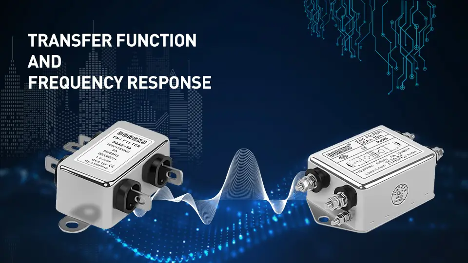
The transfer function models the output of a system based on various possible inputs. In the context of filters, it relates the output amplitude to the input frequency. Gain and phase shift are key components of the frequency response, indicating how filters modify input signals.
Frequency response reflects how the output amplitude varies with the frequency of the input signal. Stability in a system requires that all poles of the transfer function have negative real parts.
Evaluating the frequency response at different frequencies helps designers analyze the system’s behavior and ensure optimal filter performance.
Summary
Electronic filters are the backbone of modern signal processing, ensuring that only the desired frequencies make it through while unwanted components are left behind. From understanding the fundamental components to exploring the different types of filters and their applications, we’ve covered the essential aspects of electronic filters.
By mastering the principles of filter design and implementation, you can enhance the performance of your electronic devices and tackle complex signal processing challenges with confidence. Continue exploring and experimenting with different filter configurations to unlock new possibilities in your projects.
By mastering the principles of filter design and implementation, you can enhance the performance of your electronic devices and tackle complex signal processing challenges with confidence. Continue exploring and experimenting with different filter configurations to unlock new possibilities in your projects.
Frequently Asked Questions
What is the primary function of an electronic filter?
The primary function of an electronic filter is to allow certain frequencies to pass through while attenuating others, thereby improving signal quality and clarity. This selective processing is essential in various applications, ensuring optimal performance of electronic systems.
What are the fundamental components of filter circuits?
The fundamental components of filter circuits include resistors, capacitors, and inductors. These elements work together to alter the frequency response of electrical signals.
How do low-pass filters work?
Low-pass filters effectively block higher frequencies while allowing lower frequencies to pass through. The cutoff frequency is crucial as it indicates where the output signal decreases by -3dB.
What is the difference between active and passive filters?
The primary difference between active and passive filters lies in their components and capabilities; active filters incorporate operational amplifiers and require a power source, allowing for greater precision and control, while passive filters use only passive components, lack gain, and are simpler in design.
Why are digital filters important in signal processing?
Digital filters are crucial in signal processing due to their superior accuracy and flexibility, enabling programmability while remaining stable under varying conditions. This reliability enhances the overall quality and consistency of signal manipulation.
Top AC Line EMI Filter Options for Effective Protection
Best EMI Filter for LED Light: Enhance Performance & Reduce Interference



