How to Connect a Power Entry Module: Practical Wiring Guide for OEM Equipment
Connecting a power entry module involves working with mains voltage, and a mistake in wiring can damage equipment or injure the person doing the work. This guide walks through each step of connecting a PEM in single-phase AC equipment (100–240 VAC, 50/60 Hz), from identifying terminals to verifying continuity before first power-on.
1. What a Power Entry Module Does in Your Product
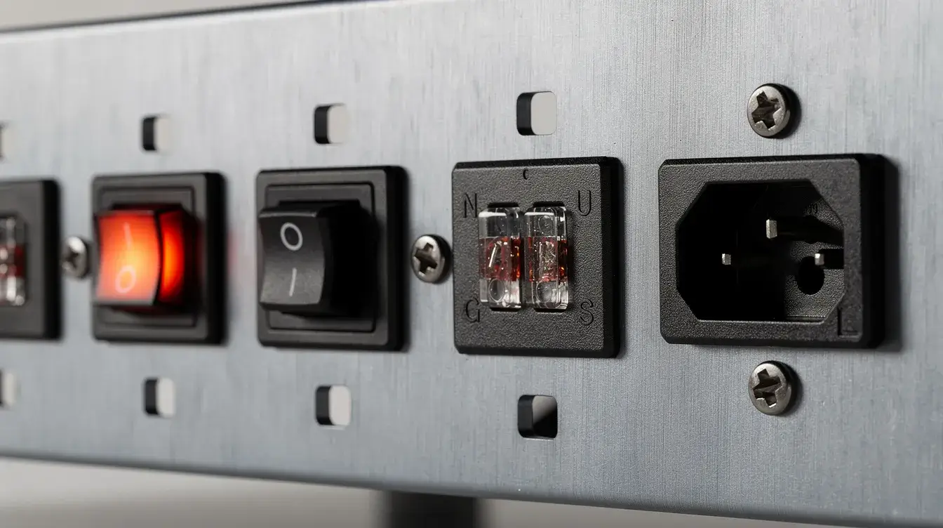
A power entry module is an integrated assembly that brings electrical power into a device while combining two to five functions in a single unit: an IEC 60320 inlet, fuse holder, power switch, EMI filter, and sometimes a voltage selector. Modules must comply with IEC 60320 standards for safety, and most carry UL, CSA, and IEC certifications. The IEC 60320 C14 inlet is the most common form factor in current OEM designs, rated for 10 A at 250 VAC.
The difference between a bare inlet and a full power entry module matters. A bare C14 inlet provides only a plug connection point; it has no circuit protection, no noise suppression, no fuse, and no switch. A complete module integrating a DOREXS EMI filter, a fuse holder with 5×20 mm fuses, and a rocker switch delivers all those functions from a compact unit that drops into a single panel cutout. Power entry modules simplify power entry in electronic devices and can reduce assembly labor costs by cutting the number of individual connections an assembler must make.
Typical applications include industrial controllers, 19-inch rack equipment, medical equipment, professional audio gear, test instruments, and home appliances. Throughout this article, examples assume single-phase AC mains. Where a design calls for an integrated IEC inlet with an EMI filter, DOREXS modules combine the inlet and filter in one assembly, which reduces external system components and simplifies EMC compliance during testing.
2. Safety First: Before You Connect a Power Entry Module
Strict safety practices are mandatory to prevent shock or equipment damage. Before touching any conductor inside the enclosure, complete every item on this list:
-
Disconnect the mains power cord assembly from the wall outlet. Use a digital multimeter to confirm 0 VAC between the line and neutral and between the line and protective earth. Typical mains voltages are 120 VAC in North America and 230 VAC in Europe, measured L–N.
-
Observe local and international safety standards before wiring any power entry. Depending on the device class, applicable standards include IEC 61010, IEC 60601-1 for medical equipment, UL/CSA, NEC, and EN 60204-1. Follow your company's lock-out/tag-out procedures.
-
Wear appropriate PPE: insulated tools, safety glasses, and an antistatic wrist strap when handling printed circuit board assemblies near EMI filters that contain charged capacitors.
-
Only qualified personnel should wire power entry modules in medical and industrial equipment. DOREXS recommends design sign-off by a responsible engineer before first power-on.
-
Never bypass fuses, protective earth (PE) connections, or EMI filter ground lugs. Removing any of these compromises both user safety and EMC compliance. Exposed high-voltage tabs must never be left bare; cover them with heat shrink tubing or insulated boots.
3. Know the Parts: Typical Power Entry Module Functions
Before wiring, identify which functional blocks your module contains. A given PEM may have from two to five functions built in.
Inlet types
The C14 inlet handles 10 A at 250 VAC and covers most desktop and rack equipment. For heavier loads, the C20 inlet supports 16–20 A. Hospital-grade variants for patient-connected medical equipment include tighter contact tolerances and are suited for low-leakage designs. Hospital-grade equipment requires low-leakage current filters of 5 µA.
EMI/RFI filter stage
An internal filter typically includes a common-mode choke, X-capacitors (line to line), and Y-capacitors (line/neutral to earth). EMI filters remove electromagnetic interference from equipment, and RFI/EMI filters prevent equipment from radiating noise back onto the mains line. Filters help provide clean electricity to medical equipment, where EMI filters are crucial for high-frequency applications that could disrupt sensitive diagnostics. Medical-grade filters reduce leakage current to 5 µA at 250 VAC, meeting the limits required for patient-connected devices.
Fuse holder options
Modules accept 5×20 mm or 6.3×32 mm fuses, in 1-pole (line only) or 2-pole (line and neutral) configurations. Double fusing is common for equipment sold in international markets where neutral grounding practices vary. Fuses must be ordered separately for power entry modules; they are not included in the box.
Switch, voltage selector, and extras
Integrated switch options include single-pole and double-pole rockers, illuminated or plain. Some modules include a voltage selector cartridge that reconfigures transformer primary windings for 115 VAC or 230 VAC operation; modern wide-range SMPS accepting 90–264 VAC often eliminate this need. Other features include filtered IEC outlets, line indicator LEDs, and V-Lock cord retention to protect the power cord assembly from accidental disconnect.


4. Decoding Terminals and Markings on a Power Entry Module
Read the module housing and datasheet before connecting a single wire. Guessing pin assignments risks swapping line and neutral, which can violate safety standards or defeat double-fuse protection.
-
Standard IEC markings: "L" for line (live), "N" for neutral, and the three-line earth symbol (⏚) for protective earth. These appear on the housing and in the datasheet figure.
-
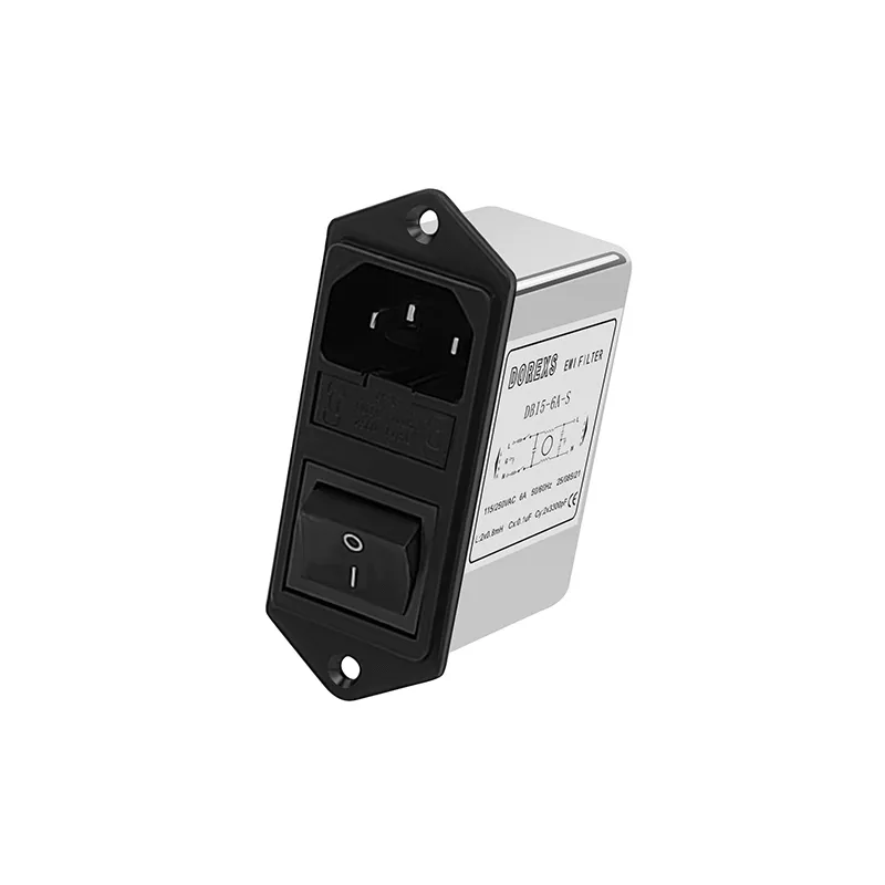
A typical DOREXS filtered/switch module labels its rear terminals as five connection points: pin 1 is line in from the IEC C14 inlet, pin 2 is line out to the load (after the filter and switch), pin 3 is neutral in, pin 4 is neutral out, and pin 5 is PE. Some modules use faston tab connectors instead of numbered pins.
-
Polarity arrows molded into the housing show current flow from inlet through fuse, switch, and filter to the load output. The voltage selector position is marked "115" or "230" on the cartridge or rotary dial.
-
Always reference the official datasheet PDF from the manufacturer. For DOREXS modules, use the 2024 or later revision to confirm terminal mapping and specifications. The DOREXS IEC inlet EMI filter page hosts current drawings.
5. Tools, Materials, and Wire Specs You'll Need
Gather these before starting work:
-
Tools: digital multimeter with continuity and AC voltage functions; wire stripper for 14–18 AWG; crimping tool for 6.3 mm (0.25 in) insulated quick-disconnect terminals; small flathead screwdriver for the fuse drawer; panel-mounting screwdriver (M3 or M4).
-
Wire: Proper gauge wire should be used based on expected current. For 10 A at 250 VAC, use at least 1.0–1.5 mm² (AWG 16–18) insulated wire rated 300/500 V. For 20 A circuits, step up to 2.5 mm² (14 AWG). PE conductors should match or exceed the line conductor gauge.
-
Consumables: fuses rated per module specifications (e.g., 5×20 mm T6.3A 250 V time-delay for a 10 A C14 module), insulated fast-on terminal crimps to cover high-voltage connections, heat shrink tubing over exposed terminals to ensure safety, and cable ties for strain relief.
-
Documentation: Have the product's system wiring diagram and component management list at hand so each connection is documented and traceable.
6. Step-by-Step: How to Connect a Power Entry Module (Basic AC Wiring)
This is the core procedure for a single-phase design. Each step assumes mains power is verified off per Section 2.
Step 1: Identify conductors.
Correct wiring standards for line and neutral must be double-checked based on regional codes. In IEC regions, brown is line, blue is neutral, and green/yellow is protective earth. In North America, black is typically line, white is neutral, and green is earth. Confirm with your local standards before proceeding.
Step 2: Mount the module in the panel.
Cut the panel opening to the dimensions listed in the DOREXS datasheet (e.g., 27.5 × 31 mm for a C14 module in 1.5 mm steel). For filtered modules, metal-to-metal contact between the module flange and the grounded panel is required for the filter's Y-capacitors to reference chassis ground properly. Installation requires verifying proper seating of the power entry module before tightening fasteners.
Step 3: Connect PE first.
The ground connection must be mechanically secure and connected to the chassis if it is conductive. Run a short, thick wire from the PEM's earth terminal to the equipment's central chassis grounding point. Proper chassis grounding is crucial for safety and electromagnetic compliance. Use star-ground practice: one central point for chassis, cable shields, and filter ground lugs. This keeps the ground loop area small and reduces conducted emissions.
Step 4: Connect line (L).
Wire the incoming mains line conductor to the PEM's line input terminal. From the PEM's line output terminal (after the internal fuse, switch, and filter), run wire leads to the equipment's internal power supply primary. The fuse must be placed on the live conductor for safety; the module's internal layout already enforces this when wired to the correct pin.
Step 5: Connect neutral (N).
Connect the incoming neutral conductor to the PEM neutral input terminal. From the neutral output, wire to the corresponding power supply neutral terminal.
Step 6: Integrate switch and filter.
In integrated modules, the internal switch and EMI filter are already wired in series between inlet and output. External wiring only needs line/neutral in and line/neutral out. Verify operation by checking continuity with the switch in the on and off position to confirm the internal path.
Step 7: Install fuses.
Open the fuse drawer with a small flat-blade screwdriver. Insert fuses of the current rating printed on the module (e.g., 6 A slow-blow for a 10 A inlet with high inrush). Confirm the holder is fully latched. Where worldwide operation requires it, install fuses in both line and neutral positions.
Step 8: Inspect and strain-relief.
Verify that all quick-disconnects are fully seated and no copper is exposed. Mechanical strain relief is important to prevent wire fatigue in power entry modules; use cable ties or clamps so vibration cannot loosen connections. Keep filter wire leads as short as possible for optimal shielding and EMC performance.

7. Using a Multi-Meter to Verify Your Wiring
Testing for continuity is essential before applying power to the device. Run these checks with the equipment unplugged.
-
Line path continuity: set the multimeter to continuity mode. With fuses installed and the switch in the on position, measure from the IEC inlet line pin to the load-side line output. You should hear a continuity beep. With the switch off, the circuit should read open.
-
Short circuit check: measure between line and neutral at the load side. Expect high resistance (megaohm range). A reading near zero indicates a short circuit that must be resolved before energizing.
-
PE continuity: measure resistance between the PEM earth terminal, chassis mounting points, and any exposed metal parts the user can access. A properly connected ground reads below 0.1–0.3 Ω.
-
Leakage current (medical): for medical equipment, perform leakage current checks per IEC 60601 or IEC 60990 using calibrated test equipment. DOREXS low-leakage filters are designed to stay within patient safety limits.
-
Insulation/hipot test: Before shipment, perform a hipot test at 1500–2500 VDC (per the applicable product safety standard) between line and chassis to confirm creepage, clearance, and wiring integrity.
8. Connecting Power Entry Modules with Extra Features
Some modules include outlets, voltage selectors, or additional filter stages. Each adds wiring considerations.
Filtered outlet: the line and neutral from the inlet pass through the filter and feed an integrated IEC outlet on the module. Downstream loads (auxiliary devices, peripherals) plug into this outlet. Respect the total current rating printed on the module; exceeding it overloads the filter and fuse. The DOREXS DBI5-S module, for example, integrates a dual fuse holder and rocker switch in a form compatible with standard panel cutouts.
Voltage selector: when a module includes a voltage selector cartridge, the transformer primary windings reconfigure between parallel (115 V) and series (230 V) based on the selector position. Matching the selector to the actual mains voltage is critical. An incorrect position at 230 VAC on a 115 V setting doubles the voltage across parallel windings, risking overheating or a blown fuse.
Separate filtered and unfiltered outputs: some PEMs offer both. Route sensitive circuits (analog front-ends, communication interfaces) through the filtered output. Motors or fans with limited noise sensitivity can use the unfiltered path. For designs where the base PEM filter is insufficient, add a DOREXS single-phase EMI filter downstream to meet medical leakage or emissions targets.
9. Optimizing Panel Space, EMC, and Component Management with DOREXS
Good connection practice feeds directly into panel space savings and component management. A compact power entry module with an integrated EMI filter, switch, and fuses replaces four or five individual components. In a 2U rack-mount instrument (88.9 mm usable height), consolidating the inlet, switch, fuse, and filter into one module can free 20–30 mm of panel width for connectors or ventilation. Power entry modules can save panel space in equipment designs where every millimeter counts. They also reduce installation labor costs by minimizing the number of connections an assembler must make.
Fewer parts simplify component management: fewer line items in ERP and BOM systems, easier purchasing, and less documentation for safety and EMC approvals. DOREXS supplies customized EMI-filtered power entry modules tuned for specific noise profiles, letting engineers eliminate additional filter printed circuit boards and external wiring.
Place the PEM where the mains cable enters the enclosure, mounted on a grounded metal panel. This keeps noisy cable runs short and reduces both radiated and conducted emissions. A surge protector or additional circuit breaker can be placed upstream in the facility's distribution panel to handle transients before they reach the module.
10. Documentation, Compliance, and When to Ask DOREXS for Help
-
Update wiring diagrams, BOM, and test records every time the power entry module type, fuse rating, or filter variant changes. Traceability matters for audits, certifications, and field service.
-
Design to applicable standards: IEC 62368-1 for IT/AV equipment, IEC 60601-1 for medical devices, and EN 55032 and EN 55011 for EMC. Use accredited test labs or in-house pre-compliance setups to validate that the connected PEM meets conducted emission and leakage specifications.
-
For DC-input power sources in a complete system, a 60-ampere circuit breaker is recommended at the DC bus to protect against overcurrent events upstream of the module.
-
Removing a power entry module can be done while the system operates in hot-swap architectures, but single-inlet designs must be de-energized first.
-
For high-risk equipment (medical devices, industrial automation in 24/7 plants, mission-critical IT), choose PEMs with certified EMI filters from manufacturers like DOREXS rather than untested imports sold separately without documentation.
-
Contact DOREXS for technical consulting: selecting the right power entry module, configuring custom EMI filters, and getting wiring and mounting instructions for new designs and redesigns.
-
Include DOREXS PEM part numbers, current ratings, and wiring diagrams directly in your internal design standards. Future projects can then reuse proven, compliant power entry solutions without repeating the selection and qualification cycle.
What Does a Power Entry Module Do? (Engineer-Focused Guide by DOREXS)
What is a Power Entry Module: Complete Guide to PEM Components and Applications