
EMI Interference Noise Rectification Case: Elevator Frequency Conversion System
This report details the process of rectifying noise interference generated by the variable frequency system of Shanghai Modern Elevator. It covers the implementation and test results of three experimental projects: radiated interference, conducted interference, and harmonic current.
The report addresses various types of electromagnetic interference encountered in elevator frequency conversion systems.
The report addresses various types of electromagnetic interference encountered in elevator frequency conversion systems.
1. Problem Introduction
Electromagnetic interference (EMI) is an ongoing challenge for modern electronic systems, especially in complex environments such as elevator inverter systems. EMI, commonly referred to as electrical noise, can disrupt the normal operation of circuits by introducing interference signals that interfere with digital and analog signals. In elevator systems, sensitive analog signals coexist with powerful digital circuits, and even tiny noise can cause serious performance issues or failures. Understanding how EMI affects signals and circuits is critical for engineers and designers to ensure reliable operation. Effective EMI mitigation is not only about meeting regulatory standards, it is also critical to the safety, efficiency, and longevity of elevator systems and the entire building infrastructure.
2. System Components and Power Supplies
Elevator inverter systems consist of several key components, including power supplies, digital circuits, and analog devices. The power supply is particularly important because it can both generate and be affected by EMI. The high-frequency signals generated by the power supply propagate through the system and can interfere with sensitive circuits and other equipment. In addition, external sources of radio frequency interference (RFI) can penetrate the system, further exacerbating EMI issues. To reduce EMI, it is critical to implement a strong filtering and shielding strategy. Decoupling capacitors are often used to filter out interference signals at the power supply end, while encapsulating the power supply in a metal housing helps shield against external interference. By carefully designing the power supply and its connections, engineers can significantly reduce the risk of EMI affecting the performance of the entire system.
3. Causes of Elevator System Interference
Interference in elevator systems can come from a variety of sources, each of which has an impact on the overall electromagnetic environment. High-frequency signals generated by power supplies or switching components introduce noise into the system, while low-frequency interference often stems from fluctuations or harmonics in the building's power system. Stray signals from other equipment in the building (such as radio transmitters, microwave ovens, or industrial machinery) may also couple into the elevator circuit and interfere with the normal operation of the elevator. To effectively reduce electromagnetic interference, it is critical to identify these interference sources and implement targeted mitigation measures. This may include installing filters to block unwanted frequencies, using shielding layers to prevent external signals from entering sensitive areas, and ensuring proper grounding of the entire system. By addressing internal and external interference sources, engineers can enhance the electromagnetic compatibility of elevator systems and ensure reliable performance.
4. Elevator Frequency Conversion System Design
The design of the elevator frequency conversion system plays a key role in minimizing electromagnetic interference. Effective EMI reduction begins with implementing proper filtering and shielding techniques. For example, integrating a low-pass filter into the power supply can prevent high-frequency signals from propagating to the rest of the system. Enclosing the system in a metal enclosure provides a physical barrier against external interference, and a carefully designed circuit board with a dedicated ground plane helps further reduce electromagnetic interference. It is also critical to carefully arrange components to minimize loop area, as larger loop areas can act as antennas, increasing the risk of radiated EMI. By considering these design principles from the beginning, engineers can create elevator inverter systems that are rugged, reliable, and compliant with electromagnetic compatibility standards.
5. Conducted Interference Rectification
Initial Filter Parameters:
3×2.0mH three-phase common-mode inductors
6×2.0uF Cx
3×0.22uF Cy
According to the customer’s EMI test results (Figure 1.1), the requirements were met after 500K, but there was a significant low-frequency exceedance. Conducted noise is a major concern in elevator systems, as it can travel along power and signal lines and disrupt circuit operation if not properly controlled.
Improvement Measures:
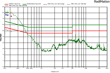
Figure 1.1
Increase X Capacitor: According to the capacitive reactance formula Xc=1/2πfc, larger capacitors filter low-frequency signals while smaller capacitors filter high-frequency signals. Considering that excessively large capacitors can lead to high leakage current and the customer's strict volume and cost constraints, the input capacitors were replaced with 3×4.7uF Cx. Network analyzer test results showed significant improvement in low-frequency performance.
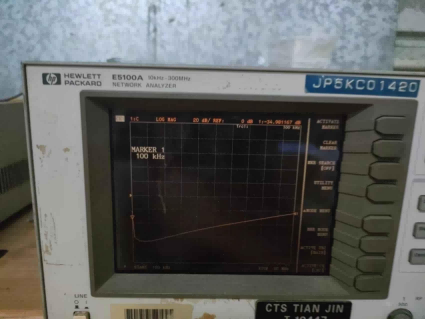
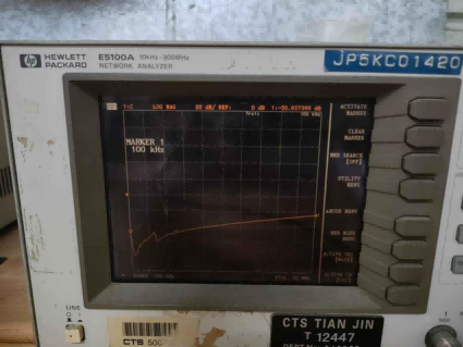
Replace Common-Mode Chokes: To ensure passing the test, we utilized amorphous core chokes known for their effectiveness in handling low-frequency interference, replacing the common-mode chokes with amorphous ones wound with 20mH inductance. Test results (Figure 1.2 common-mode and Figure 1.3 differential-mode) showed good performance, and samples were sent to Suzhou for testing.
When designing the filter and grounding system, it is important to connect all grounds at a single point. This single point connection minimizes noise and interference by preventing digital switching noise from affecting sensitive analog circuits.
 |
 |
|
| Figure 1.2 | Figure 1.3 |
6. Radiated Interference Rectification
Initial Testing
When the internal structure of the chassis was assembled and an external motor was connected as a simulated load, the test results (Figure 2.1) showed exceedances between 30M and 43M. Observations indicated that exceedances were most significant when the signal receiver faced the simulated load motor directly. Each device and electronic device in the system must be designed to minimize susceptibility to EMI, as improper component placement or grounding can amplify noise within the system. Additionally, electronic equipment must comply with EMI standards to ensure reliable operation.
 |
| Figure 2.1 |
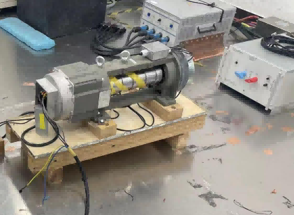
Discussions with Shanghai Modern Elevator engineers revealed that when the chassis was powered on and the variable frequency drive was operating without an external motor load, the radiated test results showed no significant exceedance. Thus, it was determined that the exposed load motor during the test became a source of radiated interference (Figure 2.2). Understanding the frequency range of EMI is crucial for selecting appropriate filtering and shielding methods to protect devices and electronic equipment.
 |
| Figure 2.2 |
Improvement Measures
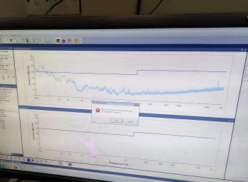
Add Ferrite Cores: Ferrite cores were added to the motor output end, with the phase wire wound 3 turns to block the motor’s interference signals. The test results (Figure 2.4) showed significant improvement, reducing noise by 10dB, though the peak shifted. Both hardware and software filtering techniques are used to ensure signals are properly filtered. Filtering strategies often include low pass filters and small capacitors to block high-frequency noise and improve signal quality.
 |
| Figure 2.4 |
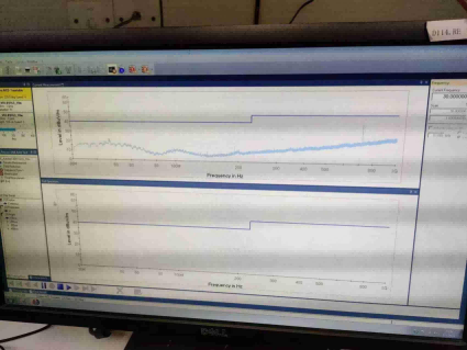
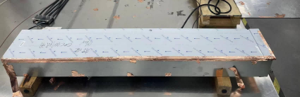
Full Shielding Treatment: Further inspection revealed that the ground wire in the shielded cable was not grounded when connecting the chassis to the power system, and the chassis insulation film was not treated (Figure 2.5). Due to limited on-site conditions, our technicians wrapped the chassis gaps and external cables with copper foil and conducted simple grounding to achieve full shielding. Test results (Figure 2.6) showed compliance with standards and successful passing of the test.
|
|
 |
|
| Figure 2.5 | Figure 2.6 |
7. Conducted Interference Rectification
Initial Testing
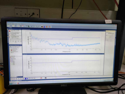
The initial test using three-phase first-order common-mode 2.0mH inductors showed unsatisfactory low-frequency filtering performance (Figure 3.1). Sources of interference in elevator systems can include a variety of factors; examples are faulty brushes, arcing, or defective power lines, all of which can generate electromagnetic interference (EMI). Long wires and cables in the system can act as antennas, picking up or radiating EMI and increasing susceptibility to noise. The transmission path of unwanted signals, such as through these wires or external conductors, can significantly affect the performance of the elevator system. High voltage spikes or arcs are also common sources that can generate substantial EMI in elevator circuits. Spurious signals may be introduced from external RF signals, which can interfere with sensitive circuits. When testing for EMI from external equipment, receiving antennas are used to measure radiated emissions from the system.
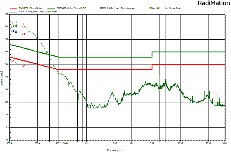 |
| Figure 3.1 |
Improvement Measures
Replace Inductors: According to the inductive reactance formula XL=2πfLXL = 2\pi fLXL=2πfL, the small inductance failed to achieve the required impedance. However, excessively large inductance could cause crosstalk, misinterpreting differential-mode signals as common-mode, severely affecting the device's anti-interference ability. Considering cost, volume, and EMI performance, three-phase first-order common-mode 20.0mH inductors were used for rectification. Test results (Figure 3.2) showed no exceedance, meeting standards and passing the test in one go.
 |
| Figure 3.2 |
8. Harmonic Current Rectification
Harmonics are mainly generated by nonlinear loads in the power grid and can usually be compensated by installing active filters. For this rectification project, our technicians identified the variable frequency system as the primary source of harmonic interference. The matched reactor helped to mitigate harmonic interference. Test results (Figure 4.1) showed that only the 5th harmonic did not meet the standard.
To further reduce electromagnetic interference (EMI), it is important to enclose the circuit inside a shielded enclosure, such as a metal box, which effectively contains electromagnetic emissions and minimizes EMI propagation. Managing input impedance is also crucial for reducing susceptibility to external noise and improving electromagnetic compatibility. In addition, op amps used in the circuit are particularly susceptible to EMI and can cause audio rectification if not properly shielded, leading to unwanted noise or distortion. Monitoring output voltage and ensuring voltage stability are essential for reliable circuit operation. Using one device with integrated EMI filtering can significantly improve system immunity to high-frequency interference.
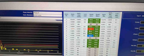 |
| Figure 4.1 |
Improvement Measures
Ferrite cores were added to the input end of the variable frequency drive, with the phase wire wound 5 turns. Test results (Figure 4.2) showed compliance with standards and passing of the test.
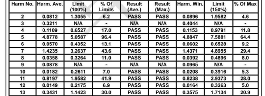 |
| Figure 4.2 |
9. Summary
Through accurate judgment and high-quality EMI filter products, this rectification successfully passed all test items. The filters demonstrated excellent anti-interference capabilities without issues such as overheating or buzzing, despite volume and cost constraints. The rectification measures and filters used in this project are applicable to a wide range of electronic products, helping ensure compliance with electromagnetic compatibility standards.
This article, with detailed steps and data analysis, demonstrates how our technicians effectively resolved the noise interference problem of the Shanghai Modern Elevator variable frequency system, providing valuable experience and reference for similar issues.
Basic Knowledge of EMI RFI Filter
EMC Filters vs Harmonic Filters: Exploring Their Roles in Electrical Systems



