How Does an EMC Filter Work-Complete Technical Guide
Introduction
EMC filters work by using passive components like inductors and capacitors to suppress electromagnetic interference, creating frequency-selective barriers that allow desired signals to pass while blocking unwanted high frequency noise. These electromagnetic compatibility filters function as low-pass circuits that maintain signal integrity for power frequencies while attenuating electromagnetic noise that could disrupt electronic equipment operation.
EMC filters operate on the principle of impedance mismatching - they present low impedance to desired signals (typically 50/60Hz AC power) and high impedance to high frequency emi that travels along power lines and signal lines.
What This Guide Covers
This guide provides comprehensive explanation of emc filter working principles, component functions, filtering mechanisms, and practical applications. We exclude filter selection procedures and installation methods, focusing specifically on the technical operation of electromagnetic interference filters.
Who This Is For
This guide is designed for electrical engineers, electronics technicians, and students seeking to understand emc filter operation principles. Whether you’re designing emi emc solutions for industrial equipment or troubleshooting electromagnetic interference issues in consumer electronics, you’ll find detailed technical insights into filter mechanisms.
Why This Matters
EMC filters are critical for device compliance with international standards like CISPR 11 and IEC 61000, preventing equipment malfunction and ensuring electromagnetic compatibility in complex electronic environments. Understanding filter operation enables proper application in power systems, medical devices, and industrial applications where electromagnetic noise can cause costly failures.
What You’ll Learn:
- EMC filter operating principles and noise suppression mechanisms
- Role of inductors and capacitors in filtering electromagnetic interference
- Frequency response characteristics and attenuation methods across different frequency ranges
- Practical working examples in real-world electronic devices and power supplies
Understanding EMC Filters and Electromagnetic Interference
EMC filters are passive electronic components that suppress electromagnetic interference while maintaining signal integrity for desired frequencies. These electromagnetic compatibility filters serve as gatekeepers in electrical systems, allowing necessary power and signals to flow while blocking unwanted noise that could disrupt sensitive electronic equipment.
Electromagnetic interference originates from various sources including switching power supplies, electric motors, and digital circuits that generate electrical noise across frequencies from 150kHz to 30MHz. This electromagnetic interference noise travels through power lines as conducted emi or radiates through space as radiated emi, potentially affecting nearby electronic devices.
The importance of electromagnetic compatibility becomes critical in environments where multiple devices operate simultaneously - from medical equipment in hospitals to industrial equipment in manufacturing facilities, where interference can cause malfunctions or safety hazards.
Types of Electromagnetic Interference
Conducted emi travels through power lines and signal lines, requiring filtering at device inputs to prevent noise from entering sensitive circuits. This interference typically occurs in the frequency range from 150kHz to 30MHz, where most emc legislation focuses regulatory attention.
Common mode noise appears on both conductors relative to ground, while differential mode noise exists between conductors. These distinct interference types require different filtering approaches - common mode chokes effectively suppress common mode noise, while capacitors handle differential mode interference between power line conductors.
This connects to emc filter design because understanding noise types determines the specific passive components and circuit topologies needed for effective suppression.
EMC Standards and Compliance Requirements
International standards like CISPR 11, EN 55011, and fcc part 15 define emission limits and immunity requirements that electronic equipment must meet. These regulations establish specific attenuation requirements across frequency ranges from 150kHz to 1GHz for most consumer electronics and industrial applications.
The federal communications commission and other regulatory bodies require emc testing to ensure compliance, making effective filtering essential for market access. Building on noise type understanding, these standards specify exactly how much attenuation filters must provide at specific frequencies.
Transition: Understanding these interference sources and regulatory requirements establishes the foundation for examining how emc filters achieve the necessary noise suppression through their core operating mechanisms.
How EMC Filters Work: Core Mechanisms
EMC filters build on the electromagnetic interference concepts by implementing frequency-selective filtering that targets unwanted noise while preserving essential power and signal transmission.
Frequency-Selective Filtering Principle
EMC filters function as low pass filters that allow desired low-frequency signals like 50/60Hz ac power to pass unimpeded through electrical systems. These filters create a cutoff frequency above which high frequency noise experiences significant attenuation, typically achieving -40dB/decade rolloff above the cutoff point.
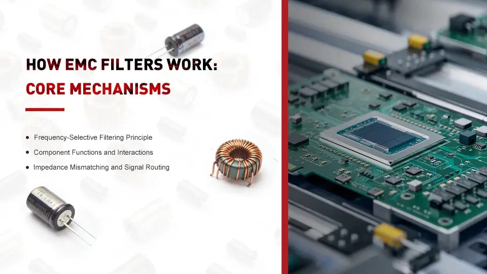
The frequency response characteristics show how filters maintain low insertion loss for power frequencies while providing substantial attenuation for higher frequencies where electromagnetic interference typically occurs. This selective response ensures normal equipment operation while eliminating problematic noise.
Impedance Mismatching and Signal Routing
Filters create impedance mismatches that reflect high frequency noise back to the noise source rather than allowing transmission to sensitive circuits. This reflection occurs because the filter presents high impedance to unwanted frequencies, creating an electrical barrier.
Capacitive elements provide low impedance paths to ground for high frequency currents, effectively shunting electromagnetic noise away from protected circuits. Unlike the reflection mechanism, this approach diverts interference to ground where it dissipates harmlessly.
Inductive elements present high impedance to high frequency signals while allowing dc and low-frequency power to pass with minimal resistance, creating frequency-dependent filtering action.
Component Functions and Interactions
X-capacitors connected line-to-line suppress differential mode noise between power conductors by providing a low-impedance bypass path for high frequency interference. These capacitors must handle line voltage while maintaining safety standards.
Y-capacitors connected line-to-ground provide common mode noise suppression with current limitations specified by safety standards for different equipment classes including medical devices. The current rating of these capacitors determines leakage current levels.
Common mode chokes use coupled inductors wound on ferrite cores to block common mode noise while allowing differential mode power flow, achieving high attenuation for specific frequencies where the choke resonates.
Key Points:
-
Frequency-selective operation separates desired signals from unwanted noise
-
Impedance mismatching reflects or diverts electromagnetic interference
-
Component synergy provides comprehensive noise suppression across target frequency ranges
Transition: These theoretical principles translate into practical filter circuits that demonstrate measurable performance in real-world applications.
EMC Filter Implementation and Circuit Design
Understanding how passive components interact leads to examining practical filter implementation where multiple elements work together to achieve required attenuation levels across various industries.
Step-by-Step: EMC Filter Operation Process
When to use this process: Analyzing how noise suppression occurs in typical single phase emi filter applications for power supplies and electronic equipment.
-
High frequency noise entry: Electromagnetic interference enters the filter circuit through power lines from external sources or device emissions, carrying unwanted energy across the target frequency range.
-
Common mode choke action: The common mode choke presents high impedance to common mode noise while allowing power frequency current to pass, effectively blocking interference that appears on both conductors simultaneously.
-
Differential mode suppression: X-capacitors shunt differential mode noise between line conductors, providing a low-impedance path that bypasses the protected equipment for high frequency interference.
-
Ground noise diversion: Y-capacitors divert remaining common mode noise to ground through a low impedance path, completing the filtering action by removing residual electromagnetic interference from the power circuit.
Comparison: Single-Stage vs Multi-Stage Filter Design
Feature |
Single-Stage Filters |
Multi-Stage Filters |
| Attenuation | 20-40dB typical | 40-80dB achievable |
| Component Count | Basic LC network | Multiple filter stages |
| Size Requirements | Compact design | Larger footprint |
| Cost Factors | Lower initial cost | Higher component cost |
| Frequency Response | Limited bandwidth | Broader attenuation range |
| Application Suitability | Basic compliance needs | Military equipment, medical applications |
Single-stage configurations work effectively for consumer electronics and basic industrial equipment where moderate attenuation meets regulatory requirements. Multi-stage designs become necessary for medical equipment, military equipment, and applications requiring superior electromagnetic compatibility across wide frequency ranges.
Transition: While these design approaches provide theoretical frameworks, practical implementation often encounters specific challenges that require targeted solutions.
Common Challenges and Solutions
Real-world emc filter applications reveal typical issues that affect performance in electronic devices ranging from power systems to wireless devices, requiring systematic approaches to maintain electromagnetic compatibility.
Challenge 1: Insufficient Attenuation at Specific Frequencies
Solution: Adjust component values to tune filter response or add additional filter stages targeting problematic frequencies in the electromagnetic environment.
This approach requires calculating resonant frequencies for inductors and capacitors, then selecting values that provide maximum attenuation where conducted emissions or immunity testing reveals deficiencies.
This approach requires calculating resonant frequencies for inductors and capacitors, then selecting values that provide maximum attenuation where conducted emissions or immunity testing reveals deficiencies.
Challenge 2: Filter Self-Resonance Reducing Effectiveness
Solution: Select passive components with self-resonant frequencies well above the target filtering range and optimize circuit layout to minimize parasitic effects.
Real-world inductors and capacitors exhibit parasitic elements that create resonances, potentially reducing filter effectiveness at higher frequencies where electromagnetic interference often occurs in everyday life applications.
Real-world inductors and capacitors exhibit parasitic elements that create resonances, potentially reducing filter effectiveness at higher frequencies where electromagnetic interference often occurs in everyday life applications.
Challenge 3: Leakage Current Exceeding Safety Limits
Solution: Reduce Y-capacitor values or use higher-rated safety capacitors to meet requirements for medical devices and other sensitive applications.
Safety standards limit leakage current for equipment classes including medical equipment, requiring careful insulation resistance calculations and component selection to maintain both filtering performance and regulatory compliance.
Transition: These practical considerations demonstrate that effective EMC filtering requires systematic understanding of both theoretical principles and real-world implementation challenges.
Safety standards limit leakage current for equipment classes including medical equipment, requiring careful insulation resistance calculations and component selection to maintain both filtering performance and regulatory compliance.
Transition: These practical considerations demonstrate that effective EMC filtering requires systematic understanding of both theoretical principles and real-world implementation challenges.
Conclusion and Next Steps
EMC filters achieve electromagnetic interference suppression through frequency-selective impedance control, using passive components to create low-pass characteristics that preserve desired signals while attenuating unwanted noise across critical frequency ranges from 150kHz to 30MHz.
The working principle centers on impedance mismatching and selective signal routing - inductors block high frequency emi while passing power frequencies, capacitors shunt noise to ground or between conductors, and the combined circuit creates the attenuation needed for electromagnetic compatibility in electronic equipment.
To get started:
-
Identify electromagnetic noise sources and target frequency ranges affecting your electronic devices
-
Calculate required attenuation levels based on conducted emissions measurements and applicable emc legislation
-
Select appropriate filter topology combining common mode chokes, X-capacitors, and Y-capacitors for your specific application
Related Topics: EMC filter selection criteria help determine optimal component values and configurations, while installation best practices ensure proper grounding and circuit integration. Measurement techniques for insertion loss and immunity testing validate filter performance in actual electromagnetic environments, supporting compliance with international standards across various industries.
What Does EMI Stand For in Electrical? Explore Electromagnetic Interference
EMI in Computer-Understanding Electromagnetic Interference and Its Impact on Computing Systems