
Ferrite Beads vs EMI Filters: Key Differences, Selection, and When to Use Each
If you’ve ever stared at a failed EMC test report wondering whether to reach for a ferrite bead or a full EMI filter, you’re not alone. Both components fight electromagnetic interference, but they do it in fundamentally different ways—and choosing wrong can cost you weeks of redesign.
This guide breaks down the key differences between ferrite beads and EMI filters, covering when each makes sense, how to select the right solution, and how to combine them effectively in modern electronic systems.
This guide breaks down the key differences between ferrite beads and EMI filters, covering when each makes sense, how to select the right solution, and how to combine them effectively in modern electronic systems.
Quick Answer: Ferrite Beads vs EMI Filters
So what’s the actual difference between ferrite beads and EMI filters?
Ferrite beads are single, lossy components designed for broadband high frequency noise suppression on individual signal lines or power rails. EMI filters, on the other hand, are multi-component networks built from inductors, capacitors, and sometimes resistors—engineered for controlled attenuation across defined frequency bands and noise modes.
Here’s what you need to know at a glance:
-
Component complexity: Ferrite beads are single passive elements; EMI filters combine multiple electronic components (typically LC filter configurations) into one network
-
Noise handling: Beads convert high frequency noise energy into heat through resistive dissipation; EMI filters create a low impedance path to ground while presenting high impedance to noise sources
-
Application level: Beads are typically PCB-trace or cable-level fixes; EMI filters (including modules from brands like DOREXS) handle tougher line-entry and compliance problems
-
Mode control: A single bead mainly affects differential mode noise; properly designed EMI filters address both common mode and differential mode simultaneously
-
Typical use case example: A ferrite bead on a 3.3V rail feeding a microcontroller vs. a 250 VAC single-phase mains EMI filter on an industrial power supply
-
The choice often comes down to this: ferrite beads are your scalpel for local, high-frequency issues; EMI filters are your heavy artillery for system-level compliance.
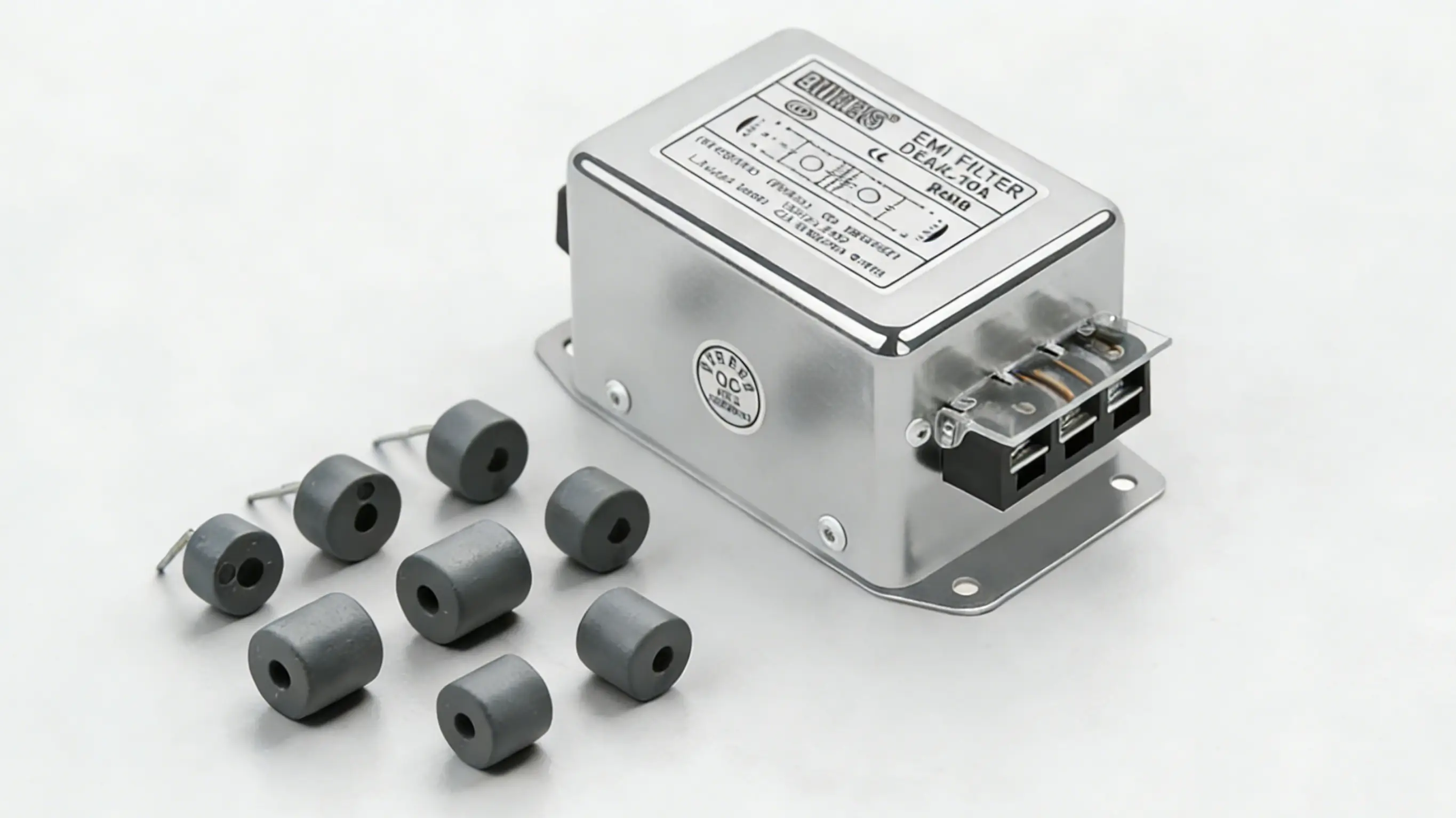
What Are Ferrite Beads?
Ferrite beads are small, lossy inductive components—often available as SMD packages (0402 through 1206) or as clip-on ferrite cores—made from manganese-zinc or nickel-zinc ferrite material. Unlike standard coil inductors, they’re specifically designed to be lossy at target frequencies.
Their behavior changes dramatically across the frequency range:
-
Low MHz range: Predominantly inductive, with a high q factor and minimal loss
-
Target band (e.g., 100 MHz): Resistive, where they dissipate noise energy as heat
-
Above self resonance frequency: Capacitive due to parasitic capacitance, with decreasing effectiveness
In that resistive operating range, ferrite beads act as a simple single-pole low pass filter when placed in series with a line. They suppress high frequency noise by converting it to thermal energy rather than reflecting it back into the circuit—a key distinction from regular inductors.
Common electrical ratings you’ll see on datasheets:
-
Impedance at 25 MHz and 100 MHz (typically 100Ω to 1000Ω)
-
DC resistance in milliohms (critical for power rails)
-
Rated current (200 mA to 6 A typical) with derating versus temperature
-
Inductance value at low frequencies
Ferrite beads are often combined with decoupling capacitors to form π-like local filters on power rails, providing additional filtering applications beyond a bead alone.
Common Applications of Ferrite Beads
-
Filtering power rails feeding FPGAs, MCUs, ADCs, and RF ICs in wireless communication systems, routers, and test instruments
-
Suppressing high frequency signals on USB, HDMI, LVDS, and MIPI signal lines in consumer electronic devices (laptops, TVs, smartphones) without severely degrading signal quality
-
Clip-on ferrite cores on laptop power cords, printer cables, or HDMI cables to reduce conducted and radiated emissions around 30–300 MHz
-
Noise suppression on switching regulator outputs in 5V/12V DC-DC converters used in telecom and industrial control boards
-
Last-minute EMC fixes on PCB traces where layout changes are expensive—adding beads in series with noisy lines or near connectors
Advantages and Limitations of Ferrite Beads
Avantages:
-
Low cost (often under $0.10 per unit)
-
Very small footprint (0402–0805 SMD packages common)
-
Easy to place late in design cycle
-
Wideband high-frequency attenuation without complex modeling in simple cases
-
No tuning required for basic filtering purposes
Limitations:
-
Limited control of exact stopband shape
-
Strong dc bias current dependency—impedance drops significantly under load
-
Reduced impedance under high current conditions
-
Potential unwanted resonance with bypass capacitors if the resonant frequency falls in a problematic frequency band
-
Risk of resonant peaking causing 10 dB gain if LC resonance falls below the crossover frequency
Ferrite beads are less effective below a few hundred kHz, making them unsuitable for low-frequency mains noise or large common-mode disturbances. Always check impedance characteristics at your actual operating current and temperature.

What Are EMI Filters?
EMI filters are multi-component networks specifically designed to attenuate conducted electromagnetic interference emi over defined frequency bands. While ferrite beads offer broadband suppression, EMI filters are engineered for precise filter response curves—typically targeting the 150 kHz to 30 MHz range specified by standards like CISPR 22/32.
For more information on the role of EMI filters in LED lighting systems, see below.
Key characteristics of EMI filters:
-
Multi-component structure: Combine inductors, capacitors, and sometimes a damping resistor in calculated arrangements
-
Mode-specific design: Separate components target differential-mode and common-mode noise independently
-
Predictable performance: Design can be simulated to achieve specific insertion loss curves (40–60 dB attenuation is common)
-
Compliance-oriented: Built to meet specific regulatory requirements
A typical line-entry AC mains EMI filter topology includes:
-
X-capacitors across line-neutral for differential-mode filtering
-
Common-mode chokes (often wound on ferrite cores) for symmetric noise
-
Y-capacitors to PE ground for common-mode suppression
EMI filters can be implemented as on-board discrete LC networks or as pre-certified modules. DOREXS, for example, offers single-phase and three-phase EMI filter units designed for industrial and telecom applications with tested insertion loss curves and safety certifications.
Types of EMI Filters
Understanding the different EMI filter architectures helps you select the right solution:
-
Single-stage LC filters: Simple C-L or L-C low pass filter network configurations used in DC-DC converters and low- to mid-power supplies
-
Two- or multi-stage EMI filters: Cascaded LC sections achieving higher attenuation (40+ dB), common in 250W–3kW industrial and medical power supplies
-
Common-mode filters: Ferrite chokes plus Y-capacitors specifically targeting noise that appears equal and in-phase on multiple conductors
-
Differential-mode filters: Series inductors and X-capacitors focused on noise between line and neutral (or between DC rails)
-
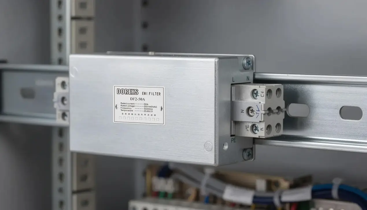
Integrated modular EMI filters: Off-the-shelf filter modules in metal housings with screw terminals—DOREXS offers these for 110/230 VAC or 380/480 VAC systems, simplifying compliance design significantly
Common EMI Filter Applications
-
AC line filters at the input of switch-mode power supplies in LED drivers, EV chargers, UPS systems, and server power shelves
-
DC-side filters in motor drives for CNC machines, HVAC blowers, and elevator control systems meeting IEC/EN 61800-3 limits
-
EMI filtering in medical equipment (patient monitors, imaging systems) requiring IEC 60601-1-2 compliance
-
Filters in household appliances (washing machines, induction cooktops, refrigerators) preventing interference with radios and Wi-Fi
-
Pre-compliance and retrofit solutions: adding a DOREXS EMI filter module to an existing product line that fails CISPR 11/22 tests at 150 kHz–10 MHz
Ferrite Beads vs EMI Filters: Key Technical Differences
The table below summarizes the core differences when comparing ferrite beads against EMI filters for your electronic circuits:
Parameter |
Ferrite Beads |
EMI Filters |
| Component count | Single element | Multiple (L, C, R networks) |
| Primary frequency coverage | ~10 MHz to 1 GHz | Both common and differential |
| Modes handled | Mainly differential (single line) | Both common and differential |
| Attenuation predictability | Moderate (material-dependent) | High (engineered to spec) |
| Current/voltage range | Low voltage, mA to few A | Up to kV levels, 1A to 100A+ |
| Typical cost per line | $0.05–$0.50 | $5–$50+ for modules |
| Heat dissipation | Converts noise to heat | Reflects/diverts noise via impedance |
| Compliance certification | Rarely certified as system | Often UL, EN, CSA certified |
Key technical distinctions to understand:
-
Ferrite beads provide broadband, mainly high-frequency attenuation but with less control over the exact filter response
-
EMI filters are engineered for specific passbands/stopbands aligned with compliance standards
-
Beads are typically single-line solutions; EMI filters often treat entire power inputs (230 VAC/16 A lines) or cable bundles
-
EMI filters can handle kilovolt-level surges and mains isolation requirements; beads are strictly low-voltage PCB or cable magnetic components
-
Beads are series elements only; EMI filters use both series inductance and shunt capacitance to create the desired low pass filtering behavior
Performance Across Frequency Range
Understanding where each solution excels in the frequency spectrum is critical for effective system design:
-
Ferrite bead sweet spot: Strongest attenuation from approximately 10 MHz up to several hundred MHz, sometimes extending past 1 GHz depending on core material and geometry—achieving 20–40 dB attenuation in the 100–500 MHz range
-
EMI filter design bands: For mains equipment, typically targeting the 150 kHz–30 MHz conducted EMI range defined by CISPR 11, CISPR 32, FCC Part 15, and similar standards
-
Lower frequency challenges: Below 150 kHz, additional measures (larger inductors, active PFC design) may be needed beyond standard EMI filters; beads are essentially ineffective at these lower frequency ranges since they remain inductive with high Q
-
Predictable compliance: DOREXS EMI filters specify tested insertion loss curves to international standards, giving designers more confidence than relying on individual ferrite bead impedance curves
When your harmonics and emi source frequencies cluster in the 150 kHz–30 MHz band, a structured EMI filter will almost always outperform scattered ferrite beads.
Mode Control: Common-Mode vs Differential-Mode
Noise in electronic systems travels in two fundamental modes, and each requires different filtering approaches:
-
A single ferrite bead on one conductor mainly impacts differential-mode noise; common-mode noise requires beads on all lines simultaneously or dedicated common-mode chokes
-
Typical EMI filter topologies explicitly separate common-mode and differential-mode control via distinct inductors and capacitors
-
In three-phase systems (400 VAC drives), dedicated three-phase EMI filter modules from manufacturers like DOREXS handle both modes across all phases and neutral
-
When compliance testing reveals dominant common-mode peaks, designers typically move from scattered beads to structured EMI filter networks with proper Y-capacitors
When to Use Ferrite Beads vs EMI Filters in Design
Making the right choice depends on your specific noise challenges and compliance requirements:
-
Use ferrite beads for: Local PCB noise issues like microcontroller reset line glitches, USB high-frequency ringing, or clock line harmonics—problems localized to specific signal lines
-
Use EMI filters for: Mains input filtering, system-level EMC compliance, and when pre-compliance tests show broadband conducted emissions exceeding limits
Practical scenario examples:
Scenario |
Recommended Solution |
| Small IoT node powered via 5V USB | Ferrite beads + layout optimization |
| 500W SMPS for 19” rack server | Dedicated line EMI filter (e.g., DOREXS module) |
| ADC reference rail with switching noise | Ferrite bead + local capacitor pi-filter |
| Industrial motor drive meeting IEC 61800-3 | Three-phase EMI filter at input |
| High-speed USB3 interface with crosstalk | Ferrite cores on cables + PCB beads |
Design flow recommendation:
-
Start with good layout and solid ground planes
-
Add ferrite beads for local suppression on sensitive lines
-
Perform pre-compliance testing around 150 kHz–30 MHz
-
Integrate or select an EMI filter (e.g., DOREXS module) based on measured gaps
-
Iterate and verify improvements with spectrum analyzer measurements
For more in-depth information, see these strategies to reduce electromagnetic interference.
Regulatory standards (CE mark, FCC, UKCA) often push designers toward certified EMI filters rather than relying solely on ferrite beads. A DOREXS certified module can simplify your compliance documentation significantly.
Regulatory standards (CE mark, FCC, UKCA) often push designers toward certified EMI filters rather than relying solely on ferrite beads. A DOREXS certified module can simplify your compliance documentation significantly.
Combining Ferrite Beads and EMI Filters
In most 2020s designs, optimal EMC performance requires both approaches working together:
-
A DOREXS line EMI filter at the AC input handles conducted emissions compliance, while ferrite beads on sensitive analog and digital rails provide additional local filtering
-
Example configuration: A 24V industrial PLC with a DIN-rail DOREXS EMI filter on the supply input, plus beads on ADC reference lines and CAN bus signals for extra robustness against high frequency noise
-
System-level EMI performance typically requires hierarchical filtering: chassis-level, board-level, and line-level components each addressing different parts of the problem
-
The combined energy management approach—EMI filter blocking mains-frequency harmonics while beads handle RF noise—covers the full range of potential interference
Stacking too many lossy magnetic components without analysis can cause detrimental issues like unintended resonance. Always verify improvements with LISNs and spectrum analyzers rather than assuming more filtering equals better performance.

Choosing and Sourcing EMI Filters and Ferrite Solutions
Selecting the right components requires understanding key parameters for each category.
For ferrite beads, evaluate:
-
Target noise frequency where suppression is needed
-
Required impedance at that frequency (check curves, not just single-point specs)
-
Allowable dc resistance (voltage drop on power rails)
-
Maximum DC current with appropriate derating
-
Package size constraints (0402, 0603, 0805, 1206)
-
Temperature range for your operating range
For EMI filters, evaluate:
-
Supply voltage requirements (110 VAC, 230 VAC, 400 VAC three-phase)
-
Rated current capacity (1A to 100A+)
-
Leakage current limits (especially critical for medical applications)
-
Required insertion loss across frequency band of interest
-
Safety approvals needed (UL, EN, CSA, IEC)
-
Mounting style (chassis-mount, PCB-mount, DIN-rail)
DOREXS manufactures ready-made EMI filter products including single-phase and three-phase AC line filters designed for industrial, telecom, and appliance markets. Their products provide:
-
Tested insertion loss curves verified to international standards
-
Safety certifications simplifying regulatory compliance
-
Standard form factors (chassis-mount, PCB-mount) for straightforward integration
-
Options for both wire leads and screw terminals
Pairing catalog EMI filters from DOREXS with PCB-level ferrite beads gives you both regulatory compliance at the system level and low noise on sensitive subsystems.
Practical Design Tips and Testing
Implementing ferrite beads and EMI filters effectively requires attention to physical design:
-
Bead placement: Position ferrite beads as close as possible to the emi source or connectors, with short, wide return paths and solid reference planes to maintain their effectiveness
-
Filter mounting: Mount EMI filters (like DOREXS chassis filters) near the power entry point with minimized lead length and solid bonding to chassis ground—long wire leads between the filter and entry point compromise performance
-
Pre-compliance testing: Perform tests using a LISN and spectrum analyzer around 150 kHz–30 MHz early in development to determine whether beads alone are sufficient or a dedicated EMI filter is required
-
Iterative approach: Adjust bead values, filter topology, and grounding schemes based on measured emission plots rather than relying solely on simulations—real-world parasitic capacitance and layout effects often differ from models
-
Holistic EMC: Proper cabling, shielding, and layout work hand-in-hand with ferrite beads and EMI filters; no amount of filtering compensates for a fundamentally poor layout with inadequate ground planes
Per app note recommendations from major semiconductor vendors, improper use of ferrite beads—particularly creating LC resonance with nearby capacitors at frequencies below the bead’s crossover frequency—can actually amplify noise by 10 dB or more. Always verify with measurements.
Key Takeaways
-
Ferrite beads are single lossy elements that suppress high frequency noise through resistive dissipation, ideal for PCB-level fixes above 10 MHz
-
EMI filters are multi-component networks designed for controlled attenuation across specific frequency bands, essential for compliance with CISPR, FCC, and IEC standards
-
Beads excel at local, high-frequency problems; EMI filters handle system-level conducted emissions across both common and differential modes
-
Modern designs often combine both: DOREXS EMI filter modules at power entry points plus ferrite beads on sensitive signal and power lines
-
Selection requires matching component characteristics to your specific noise frequencies, current requirements, and compliance targets
-
Always verify filter effectiveness with actual measurements—simulations and datasheet curves only tell part of the story
Understanding when to reach for a ferrite bead versus a full EMI filter can save weeks of redesign and prevent costly failed compliance tests. Start with solid layout practices, perform pre-compliance testing early, and select the right combination of beads and filters for your specific noise challenges.
If you’re facing conducted emissions issues on industrial or telecom equipment, consider evaluating DOREXS EMI filter products as part of your compliance strategy—their certified modules combined with strategic ferrite bead placement can help you pass EMC testing on the first attempt.
EMC Challenges in Battery Energy Storage
EMI Issues and Solutions in Medical Devices



